Congratulations on your choice to use Sigasi Visual HDL™ (or Sigasi for short), the leading HDL platform for Verilog, SystemVerilog, and VHDL. Sigasi is a world-class productivity tool integrating smoothly with industry tools such as Xilinx Vivado, Siemens Questa, and Synopsys VCS. It allows you to focus on the big-picture design, while it takes care of the syntax and semantics of your code.
This “Getting started” guide helps you set up Sigasi and teaches you the basics of working with projects. Let’s get your productivity journey started.
1.1. Installation
To begin using Sigasi, you must first ensure your environment is
properly configured. This page outlines the hardware and software prerequisites
followed by step-by-step instructions for installing the extension in VS Code.
Sigasi requires VS Code version 1.82.0 or higher. Our extension is
known to work on clones of VS Code like VS Codium ,
Cursor , Antigravity , etc.
Do note that we only deeply test on VS Code proper, so your mileage may vary.
If you have not done so already, follow these instructions to install VS Code.
Next, install the Sigasi extension from within VS Code:
Open the Extensions pane using Ctrl+Shift+X
In the Search field at the top, type Sigasi
Click Install on the
VHDL & SystemVerilog IDE by Sigasi
extension
Before the extension is installed, VS Code verifies that you trust the publisher. Verify the publisher is indeed Sigasi and click Trust Publisher & Install.
VS Code automatically updates extensions by default.
Since VS Code version 1.85, fine-grained control over which extensions to auto-update is available. You can right-click on the Sigasi extension in the Extensions pane and toggle the Auto Update option.
1.2. License setup
Congratulations, you have installed Sigasi. Your next step is to configure a license. Here you have two options:
Use Sigasi with a commercial license. Multiple license tiers are available as detailed here. You can obtain a commercial license by requesting a trial or contacting our sales team.
Use Sigasi in Community Edition mode. In this mode, you can use all of Sigasi’s extensive features for free, but with restrictions (see lower down).
The first line starts with INCREMENT. If it starts with SERVER or DAEMON, you’re dealing with a floating license.
Save the license that was sent to you in a file, e.g., sigasi.lic.
You can set the path to your license file through the sigasi.pathToLicense
setting.
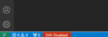
Navigate to this setting by hovering over the status bar item at the bottom of your window indicating SVH Disabled.
Then click the Configure Your License button in the pop-up to open the license settings.
Type the path to your license file (e.g., /home/user/sigasi.lic) in the box under Sigasi: Path to License.
The first line starts with SERVER or DAEMON. If it starts with INCREMENT, you’re dealing with a node-locked license.
Sigasi’s license key management system is based on the well-known FlexNet (a.k.a. FlexLM) license manager.
Using a floating license requires you to first set up a FlexNet license server, for which you can refer to our guide.
If you have multiple floating license files, you can combine them by copying the INCREMENT part of the second file into the first. For example:
You can set the path to your license server through the sigasi.pathToLicense
setting.
To navigate to this setting, you can hover over the status bar item at the bottom of your window indicating SVH Disabled.
After clicking on the Configure Your License button in the hover, the license settings will be opened.
Type the path to your license server (e.g., <portnumber>@<servername>) in the box under Sigasi: Path to License. For example:
TEXT
27000@myserver.example.com
If you have redundant license servers, enter each of the license servers separated by a comma.
We recommend you specify the primary server first in the list, as the first item in the list is checked first.
For example:
If you have multiple, non-redundant license servers, the servers should be separated using colons (:) on Linux and semicolons (;) on Windows.
When you leave Sigasi: Path to License empty, Sigasi tries to use an environment variable
to find the license server. If this fails, it will look for a .sigasi.lic file in your home folder.
You can also set your license server via an environment variable instead of configuring it in Sigasi.
Both $SIGASI_LM_LICENSE_FILE and $LM_LICENSE_FILE are supported.
When $SIGASI_LM_LICENSE_FILE is set, $LM_LICENSE_FILE is ignored. $LM_LICENSE_FILE is a general FlexNet environment variable that is also interpreted by other software from differing vendors.
Note that if you want to use an environment variable, the sigasi.pathToLicense
setting should be cleared, as that path is prioritized.
For redundant license servers, the servers should be separated using commas (,).
We recommend you specify the primary server first in the list.
For example:
The Sigasi edition is controlled by the license key.
Sigasi will automatically upgrade the license to the
edition that is required for the requested feature.
For example, when first using the Block Diagram, Sigasi will bump your license from Designer to Professional.
Sigasi holds on to the acquired license after upgrading, unless you manually downgrade the license again.
You can downgrade the license through the Downgrade to ... Edition button in the license status bar item.
The license status bar item can be found at the bottom of the window, indicating the current edition that is in use.
After downgrading, all views that require a higher edition will be disabled. These views will show buttons to upgrade the license again.
In Community Edition mode, you can use all of Sigasi Visual HDL Enterprise Edition
’s extensive
features for free, with exception of the CLI and settings sharing. The Community Edition is typically aimed at students,
hobbyists, educators, etc. who want to enjoy a world-class editing experience.
There are three important things to note though:
We gather usage statistics and send those to Sigasi servers to
continuously improve our product.
We ask you for an email address, which we’ll use to provide you with a
tasteful amount of product news.
Most importantly, you must be a non-commercial user, as detailed in our
EULA.
You can enable the Community Edition by opening the license setup page
through the command palette: press Ctrl+Shift+Pand type Sigasi: Open License
Setup Page. On the right of the page, you’ll see:
Fill out the form and you are good to go.
Some final things to note:
The Community Edition license will not activate if you have a commercial
license configured. For example, if in the license settings, Sigasi
finds a mention of a FlexNet server, the Community Edition will not
activate.
When you restart VS Code, you will regularly see a reminder that you are
using the Community Edition.
The Community Edition requires access to Sigasi’s servers. If a
connection cannot be established to upload some usage statistics, Community
Edition will be deactivated.
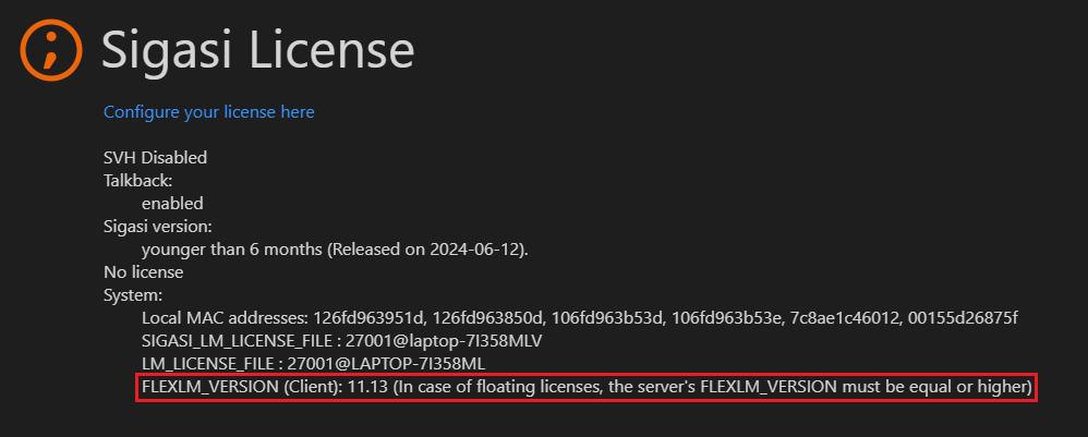
If you’re having trouble setting up your license, you can open the license diagnostic page. It can be opened by clicking on the license status bar item at the bottom of your window.
1.3. Layout
The Sigasi extension is built on top of VS Code. It is useful to review the layout of a typical VS Code window before we zoom in on how Sigasi fits in.
The screenshot below shows the different areas in a VS Code window. VS Code extensions can contribute items to every panel except the Title Bar. You can hide and show each of the areas.
Title Bar: The topmost bar. It contains layout controls and the command center to search and execute tasks.
Activity Bar: The leftmost bar. It contains activity items for installed extensions, including the Sigasi View
.
Primary Side Bar: The primary collapsible sidebar. It displays items depending on the activity that is selected in the Activity Bar. It contains items such as the Explorer, the Projects View, the Design Hierarchy, and the Libraries View.
Editor: The main editing area for your files.
Overiew Ruler: The rightmost vertical bar in the editor. Shows problem markers, todo’s, highlights, etc.
Panel: The panel below the Editor area containing useful views such as the Problems and Terminal view.
Secondary Side Bar: A secondary collapsible sidebar. Its items are independent of any selection. It contains items such as the Copilot Chat and the Outline.
Status Bar: The bottommost bar. It shows the status of VS Code, Sigasi, and of other extensions.
Most items can be dragged and dropped between the Activity Bar, the Panel, and the two Side Bars.
1.4. Hello world project
Now that you have a working setup, let’s put Sigasi through its paces. We’ll start by creating a “Hello World” project to showcase the basics of project creation.
First, create a folder called hello-world in a location that suits you. Now, start VS Code and open the hello-world folder (File > Open Folder...).
You should see an empty VS Code workspace focused on the Explorer Activity. The real action happens in the Sigasi Activity, indicated by the Sigasi logo,
.
Here you are prompted to create or open a project. Click the Create or Open a Project button to initialize the project in the hello-world folder.
If you switch to the Explorer, you will find that the hello-world folder now contains a project.sigasi file. This is where Sigasi stores the project description. Sigasi also opens project.sigasi in the editor so you can inspect or edit it directly. In general, when you open a folder containing a project.sigasi file, Sigasi will automatically start.
The hello-world project is now shown in the Projects View. Currently, it is empty except for the Targets folder, which contains information about how the project is being built. You can ignore this folder for now.
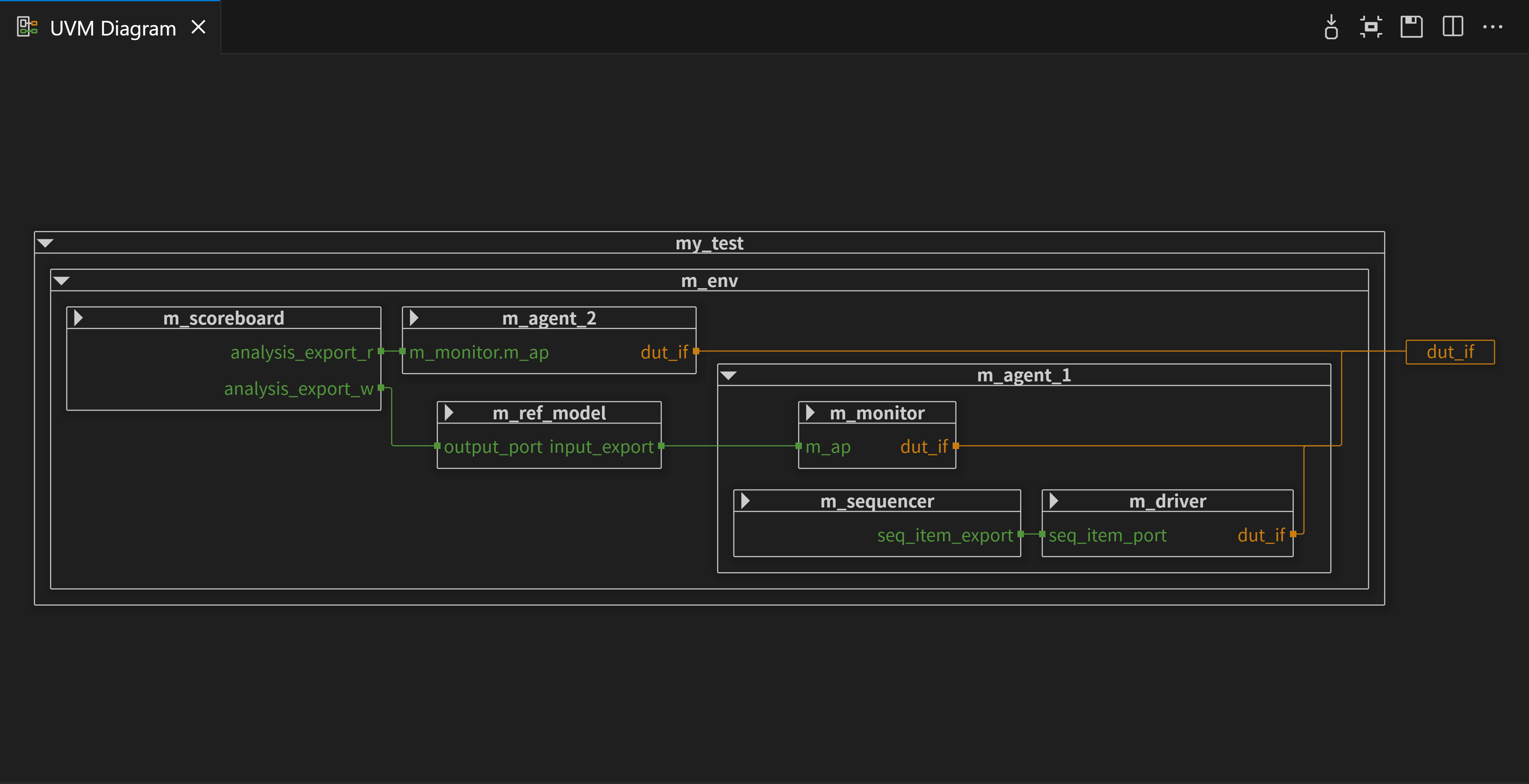
What else is there? There are also the Design Hierarchy, UVM Topology, and Libraries views. Let’s have a quick look at the Libraries View.
At the moment, no libraries are listed. As you develop your project, you will populate this view with your own libraries and design units.
Now, let’s add some content. We’ll create one SystemVerilog file and one VHDL file to demonstrate the simplest use case. Right-click the hello-world node in the Projects View and select New File…. Name the file verilog_hello.sv. Because of the .sv extension, Sigasi recognizes it as a SystemVerilog file.
You will notice a small yellow squiggle at the top of the file. This is a warning from Sigasi. Hovering over the squiggle reveals a hint.
It says “File must be mapped to a library for Sigasi analysis”, indicating that the file is not yet being analyzed. To enable full support, the file must be assigned to a library.
You can also inspect these warnings in the Problems View (View > Problems).
To fix the problem, hover over the squiggle again and select Configure Library for this Project…. This allows you to set a default library for the entire project. Enter the library name hello_lib. The warning will disappear as Sigasi begins analyzing the file. Any new files added to the project will now be automatically assigned to hello_lib.
If you look at the Libraries View again, hello_lib will now be visible. The Libraries View only shows libraries that are currently in use.
Next, let’s add a module declaration. Place your cursor in the editor and press Ctrl+Spaceto open Content Assist. Start typing module and press Enter when the module template is selected. Sigasi will insert a module skeleton for you.
Note that Sigasi automatically names the module verilog_hello to match the filename. It also flags clk and rst as unused ports—a helpful linting feature we will explore later.
To properly set up Verilog projects, you often need to configure include paths. First, create a folder called include_dir by right-clicking the project node and selecting New Folder…. To tell Sigasi to use this folder for includes, right-click include_dir and select Configure > Add to Include Paths.
Now, any files created in include_dir can be included in your Verilog files. For example, if you add my_include_file.svh to include_dir, typing `include "my_include_file.svh" will be correctly recognized.
Finally, let’s create a VHDL file. Right-click hello-world in the Projects View and select New File…. Name it vhdl_hello.vhd.
Notice that vhdl_hello.vhd is already mapped to hello_lib because we previously assigned the entire project to that library.
Also notice that a new folder appeared called VHDL Standard Libraries[2019]. This folder contains standard VHDL libraries such as standard.vhdl and textio.vhdl. These files are virtual and do not exist on your physical disk; they are provided so you can consult standard definitions when needed.
You will also notice these libraries appeared in the Libraries View.
To add content, place your cursor in the empty file, press Ctrl+Space, and type entity/arch.... Select the entity/architecture pair template. Just like with SystemVerilog, Sigasi creates the boilerplate for you, naming the entity vhdl_hello.
When you are ready to share your hello-world project with colleagues, remember to check the project description into your version control system. For Sigasi, you should include the project.sigasi file. If you have configured any linting rules or other settings, also include the .sigasi directory, except for .sigasi/generated, which contains log files and other debug information. See Creating Modular Projects for details.
1.5. Tutorial & demo
An excellent way to get started with Sigasi and getting the hang of
its most essential features, is by going through the interactive tutorial
or by playing around with a real-life demo project.
The Tutorial Project is a little project that has been handcrafted to
showcase a number of Sigasi features. It’s not a real-life project.
Even worse, we’ve inserted a number of serious issues (even syntax issues!) to
show Sigasi in action. You can create the Tutorial Project straight
from within VS Code. Go to the
Sigasi View. When no project is open yet,
the tutorial can be created through the link shown below.
Alternatively, the same can be achieved through the Sigasi: New Tutorial
Project… command.
You will be prompted to type a name for your tutorial project, after which the
tutorial will be opened in a new window.
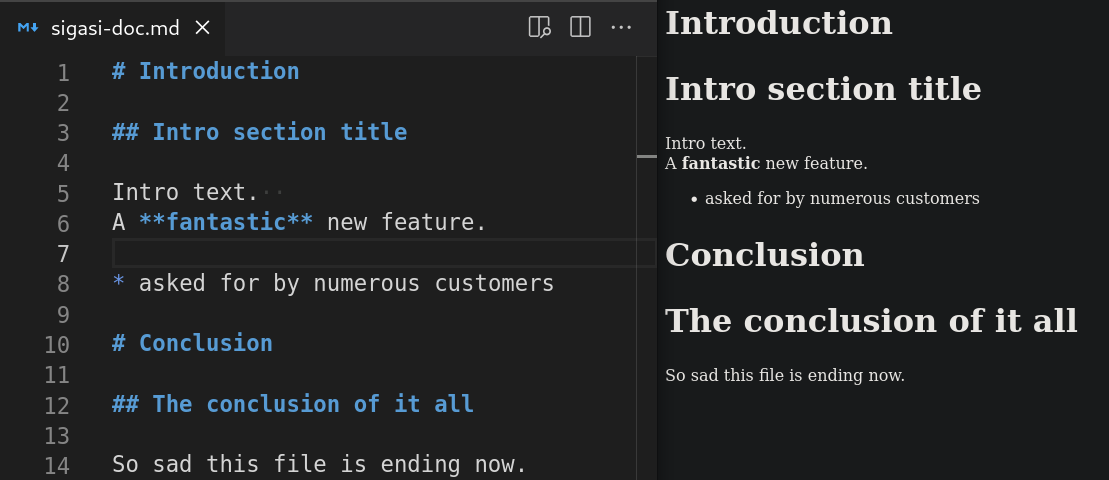
The tutorial is written in Markdown format. Push the Open the Preview to the Side
button to get a nicely formatted version. Now go through the tutorial.
You will find a number of TODO entries embedded in the HDL files. These will
guide you to explore the many features of Sigasi.
Maybe you’ve had enough of “toy” examples and instead want to see a real,
industrial project? Enter the command Sigasi: Create Demo Project…. It
will create for you a pre-configured version of the SweRV
project , a real-world
RISC-V core from Western Digital.
2. Projects
In Sigasi, a project is the fundamental unit used to define how your HDL code is analyzed and understood. While you can open individual files in VS Code, Sigasi works best when your files are part of a project.
Projects are essential for effective design and collaboration:
Global Analysis: Sigasi analyzes how all your source files connect, enabling powerful features like project-wide reference tracking, navigation to declarations, and accurate type checking across your entire design.
SystemVerilog Preprocessing: SystemVerilog files often rely on macros and include files defined elsewhere. A project provides the necessary preprocessor environment (include paths and initial defines) for accurate analysis.
Scope Definition: A project defines exactly which files are relevant to your design and which should be ignored, preventing unnecessary analysis of unrelated files.
Shared Configuration: A project serves as a central location to store settings such as language versions, library mappings, and linting rules. Because these configuration files are stored on disk, they can be checked into your source control system (like Git) to ensure the entire team uses the exact same setup.
Sigasi supports two project formats. Modular Projects are the default and recommended format for new work; Classic Projects remain supported for existing setups.
Modular projects store their configuration in a project.sigasi (or .sigasi/project.sigasi) file.
Why they exist: To support modern HDL workflows, such as scripted builds, multiple build targets, and advanced dependency management.
Key Features:
Multiple Build Targets: Modular projects support multiple build targets (e.g., separate targets for RTL and testbenches) that can depend on each other. This allows a testbench target to “see” and use design units from an RTL target without duplicating configuration.
Scripted Targets: Large HDL projects often use dedicated build systems like Makefiles or Bazel. Through Scripted Targets, Sigasi can consume these descriptions to stay in sync with your external build environment as the project evolves.
Who they are for: All new projects, regardless of size or complexity.
Classic projects use the .project and .library_mapping.xml files and a .settings folder to describe the project’s structure.
Why they exist: They predate Modular Projects and provide a file-system-based mapping approach that’s still in use across many existing codebases.
Who they are for: Teams maintaining existing Classic project setups. For new projects, use Modular Projects instead.
2.1. Modular Projects
Modular Projects are the default project format in Sigasi.
The format was introduced in Sigasi Visual HDL 2025.3 and promoted to the default in Sigasi Visual HDL 2026.2.
On top of the capabilities of the legacy Classic Projects,
Modular Projects offer a few key benefits:
They can be created based on your existing project configuration,
such as a makefile, a Bazel-script, a Vivado project, or a VUnit configuration.
You can split up your project into reusable IP through targets and dependencies.
To create a new, empty, Modular Project, use the Create or Open
Project… button in the Projects View.
A file browser opens, in which you can create an empty directory and select it, or select a folder containing an existing codebase to import into Sigasi.
Regardless of the contents of the selected folder, Sigasi will create a project.sigasi in the folder and open it for you.
It should contain JSON contents similar to these:
The project name is taken from the name of the chosen directory and can be changed here or by right-clicking the project in the Projects View and selecting Rename.
The project version is optional, but recommended because it’s important for dependency resolution.
After that, you’ll find the definition of the hdl target.
A target comprises a self-contained set of files that are compiled together—you can read more on them in the next section.
This particular target isn’t doing much.
It only contains a library mapping, which details how HDL files are assigned to libraries.
Library mapping contains a detailed explanation.
For now, you might simply want to map your whole project to the work library by replacing "": [] with "": "work" or,
if you have a very large project, map everything in a single folder using "path/to/folder": "work" instead.
Alternatively, right-click on folders and files in the Projects view to Change Library.
When using a version control system such as git,
you likely want to inform the version control system which project configuration files need to be tracked.
You definitely want to add the project.sigasi file,
because that describes to others (even when not using Sigasi) how to build your project.
When you’re changing e.g. linting rule configuration,
we’ll store those in the .sigasi directory in your project directory,
so tracking those will help your colleagues use the same styling rules, etc.
You don’t want to track.sigasi/generated though:
this directory contains log files and other debug information on Scripted targets which could contain timestamps etc.
The files and directories here change often and contain machine-specific details.
2.1.2. Transitioning from Classic Projects
Classic Projects can be easily translated to Modular Projects
by using a manual target.
A manual target allows you to manually define library mapping, language version, include directories, etc. just as you would with Classic Projects.
Since Modular Projects work a bit differently, some workflows don’t carry over one-to-one to. This guide explains the equivalent workflows in Modular Projects.
Classic Projects remain fully supported.
You don’t have to migrate, but we recommend doing so as the Classic format can no longer be evolved and Classic Projects can not be included in dependencies from Modular Projects. Features such as settings sharing and scripted targets cannot be supported by Classic Projects.
In Classic Projects, Common Libraries is a virtual folder for the VHDL standard
libraries and reusable external HDL files. Its files are superficially
analyzed, never linted.
Modular Projects no longer use this folder, instead:
Standard libraries (std, ieee) are provided automatically, under an immutable
VHDL Standard Libraries node.
External source and pre-extracted libraries become dependencies.
In Classic Projects, you could depend on an external source tree by dragging its
folder into Common Libraries as a linked folder.
In Modular Projects, you can use Dependencies instead:
you can depend on another target (within the same project or from another project),
or a library from the Library Database.
The dependency’s definitions become available to your target while its sources are
analyzed on their own. Just like Common Libraries, you get no linting noise from code
you don’t own.
Add a dependency by right-clicking a project or target and choosing Add Dependency,
or edit the dependencies field in project.sigasi.
In Classic Projects, you could extract tool and verification libraries (Vivado,
Quartus, UVM, UVVM) into the Tools and Libraries Database, then enable them on the
Common Libraries settings page.
The Tools and Libraries Database
is unchanged, you extract and manage libraries there as before. Only how you use
them changes: instead of modifying the Common Libraries settings page, add a library from the
database as a dependency, e.g., a UVM version, or
Vivado’s unisim.
In Classic Projects, Linked Resources
pulled in files from outside the project tree, and ENV- variables kept those
paths portable across machines.
Modular Projects do not support linked resources. Instead, you can point a target’s
directory at the external
location; its libraryMapping,
override, and
includeDirectories
paths resolve from there, and Sigasi scans it as part of the target. For a
self-contained, reusable tree, model it as its own target or project and pull it in
as a dependency.
Instead of ENV- prefixes, use environment variable substitution.
You can use environment variables like $VAR, ${VAR}, or
${VAR:default} in the directory field.
For example, a Classic Project’s ENV-HOME path becomes ${HOME}/....
To define variables that travel with
the project, use the environment field in project.sigasi.
In a Classic Project there were no targets: all files were mapped to libraries and
analyzed as one unit. A Modular Project shows a Targets node instead.
A target is a self-contained set of files that Sigasi compiles and
analyzes together. All targets are listed under the Targets node in the Projects view.
Your whole Classic Project maps to a single target. A Modular Project created from an
existing codebase starts with exactly that: one target (named rtl by default) whose
library mapping does what your Classic Project’s mapping did. If that’s all you need, you can
ignore the node.
Targets let you split a design into independently-compiled units. For example rtl
and tb, or synthesis and simulation connected with
dependencies. There are two kinds:
Manual targets declaratively map files to
libraries; similar to a Classic Project.
Scripted targets reuse existing build scripts
(a Makefile, a simulator do-file, …) to derive the structure.
A Classic Project spreads its configuration across the .project (the Eclipse project
description) and .library_mapping.xml files (library assignments), and a .settings folder
full of .prefs files. These are all in Eclipse’s XML and .prefs formats.
A Modular Project uses two JSONC (JSON
with comments) files instead:
.sigasi/settings.json that defines linting and
formatting preferences, tunable per target, folder, or file.
Let’s map out where each Classic Project configuration file goes:
Classic Project file
What it held
Modular Project equivalent
.project
Project name, folder structure, and linked resources
project.sigasi
.library_mapping.xml
Which files and folders map to which library
The libraryMapping section of each target in project.sigasi
.settings/ (*.prefs)
Linting and formatting preferences
.sigasi/settings.json
.settings/ (*.prefs)
Compiler options: language version, preprocessor include dirs and defines, VHDL conditional analysis
The languageMapping, verilogPreprocessor, and vhdlConditionalAnalysis fields of the relevant target in project.sigasi
If you were using a minimal project setup that only had a .project file, no .library_mapping.xml or .settings,
you can also drag your sigasi.project into the .sigasi folder.
Scripts that depend on the exact location or format of the .project,
.library_mapping.xml, or the .settings/*.prefs files will no longer work.
Point them at project.sigasi and .sigasi/settings.json instead. The JSONC
format is easier to generate and manipulate than Eclipse’s XML and .prefs.
Again, the JSON contains the name of the project, its version, and targets.
The targets are somewhat more complicated here, though.
The first target is called rtl and describes how Sigasi should interpret the RTL code of the project.
Instead of a library mapping, it configures two commands invoking a simulator: vcs -f ip/list.f and vcs -f src/list.f.
In what are called Scripted targets,
Sigasi figures out the structure of your project by reusing the existing project’s build system.
This target also defines custom environment variables that might be used in the commands,
and continues executing commands even if the return code isn’t 0.
The second target is called tb.
You can find a manually defined library mapping in its definition,
which makes it a Manual target.
The files in the testbench/src folder and its subfolders are all assigned to the testbench library,
except files with a path matching **/sim/*.
Note that the tb target does not stand on its own.
It’s a UVM testbench for the RTL code in the project,
so its source code depends on the rtl target and the UVM 1.2 library shipped with Sigasi.
You can add Dependencies on other targets in the same project, targets in another project,
and libraries from the Library Database.
To conclude:
Use Scripted targets if you already have a build configuration that you can reuse
Use Manual targets if you want full manual control or can reuse a lot of IP.
2.1.4. Manual targets
Manual targets can be used when you want Sigasi to be in the driver seat and be the main source of information on how to build a design.
They provide control similar to Classic Projects, but allow specifying everything in a single place,
and benefit from the Dependencies mechanism provided by Modular Projects.
This makes them perfect for projects where a lot of IP is reused.
The following project configuration contains a single manual target with all possible configurable items and their default values.
The first key is libraryMapping.
It is the only required key for a manual target.
When a new project is created, everything is mapped to the empty list (no libraries).
You can read more on Library mapping in the next part.
The directory key sets the base directory of the target.
Relative paths elsewhere in this target will be resolved from this directory.
By default, the project directory is used.
The dependencies and fragment keys are shared with Scripted targets,
and documented separately on the Dependencies page.
A target fragment will not be validated by itself,
but in context of the targets depending on it.
The ignore list follows a .gitignore pattern format to exclude files from consideration.
The patterns are matched relative to the target’s base directory.
You can use this setting to simplify your library mapping,
or to exclude some very large directories in your project to improve performance.
The languageMapping lets you specify which files are considered Verilog, SystemVerilog or VHDL and,
for the latter, which VHDL version they are written in.
You can configure this for the whole target, and override it for individual files or folders.
The language mapping is most easily configured by right-clicking in the Projects View.
Language mapping contains more information on this topic.
Finally, the verilogPreprocessor and vhdlConditionalAnalysis keys configure the Verilog and SystemVerilog preprocessor and VHDL conditional analysis.
You can edit these here manually or use the Target settings graphical configuration page.
2.1.4.1. Library mapping
Both in VHDL and SystemVerilog design units, functions, types, modules, etc.
are stored in “libraries”. For example, VHDL makes information related to
floating point available through the ieee.std_logic_1164 library. Or, for
SystemVerilog, you would compile your files into a library like so: vlog -work my_lib_name source_file.sv.
Whatever the mechanism, Sigasi will only consider your HDL files as
being part of a project if they are assigned to a library. If HDL files are
not assigned to a library, Sigasi’s functionality will be largely
disabled. Only some syntax highlighting will be offered, and a hint will be
provided to assign your file to a library.
We call the act of assigning an HDL file to a library “library mapping”.
To change the library mapping, you can use the right-click menu in the Projects view and select Change Library as shown in the image below.
You can right-click on individual files, folders, or a selection containing multiple files and/or folders, as well as the entire project folder.
If multiple targets are available, a dialog will prompt you to select one.
This step is skipped if there’s only one target available, such as when right-clicking on items in the Targets perspective.
Next, you can either select an existing library or type a new library name.
If you type a new name, a new library will be created and the selected items will be added to it.
To use an existing library, simply pick one from the list (for example, work)
If you want to remove files/folders from a target, select Remove from Build.
Note that the removed resource(s) will still be visible in the Projects view, and you can still add them (Change Library) to the project.
Creating new libraries, adding a file/folder to an existing library, or excluding files/folders from the build will modify your project’s project.sigasi file.
For Verilog and SystemVerilog, you can configure which file suffixes are considered Verilog, and which SystemVerilog, in the project configuration file.
By default, files ending in .v are considered Verilog and files ending in .sv are considered SystemVerilog:
If you want to change the language mapping for folders or individual Verilog files,
you can use the override key:
JSONC
"languageMapping":{"verilogSuffix":[".v"],"systemverilogSuffix":[".sv"],"override":{"testbench":"systemverilog-2012",// verilogSuffix files in the testbench folder are SystemVerilog 2012
// or
"testdata":{"vhdl":"vhdl-2019",// set the VHDL version for the testdata folder
"verilog":"systemverilog-2012",// verilogSuffix files in the testdata folder are SystemVerilog 2012
}}},
To change the VHDL version, right-click on a project, folder, or file in the Projects View and click Configure > Language Version.
If there is more than one target available, you will be prompted to select one.
Then, you can select a VHDL version for your project, folder, or file.
2.1.4.3. Target settings
The Target Settings page provides a convenient way to modify the initial state of the Verilog/SystemVerilog preprocessor and to add or remove VHDL conditional variables for VHDL 2019.
To access it, you can hover over the Targets folder or an individual target, and click the icon or you can right-click any target in the Targets section of the Projects View, and then select Target Settings.
Note that Verilog/SystemVerilog include paths must be relative to the Target Directory field, or to the project location if this field is not specified.
Note: Some conditional variables are reserved and hardcoded as required by the VHDL Language Reference Manual.
2.1.5. Scripted targets
Many EDA projects have build scripts that start simulations.
These build scripts already contain a detailed description of the designs your team is working on.
Using Modular Project scripted targets, you can avoid duplicating the information already present in your build scripts:
Sigasi will extract all relevant information from the build scripts themselves,
and automatically remain in sync with them.
To capture and record the semantics of the build scripts specified in scripted targets, Sigasi executes them in a prepared shell environment.
There, the simulators or compilers (the tools) are shadowed by so-called stub implementations.
These stubs capture the command invocations and their execution context as a compilation log.
Subsequently, the captured compilation log is interpreted and converted into a detailed compilation plan
that contains all participating files and directories in the order of their appearance.
The compilation plan is used to derive the underlying logical structure of the target.
The mechanism is generally agnostic to the chosen build technology as long as it launches the supported tools
as external processes from a regular shell environment by their simple executable name.
To consult the tools that are natively supported and that can be introspected by Sigasi on Linux and Windows, refer to our list of supported compilers.
It should be noted that the tool stubs do not call the original tool. They do not create any artifacts besides adding information to the compilation log.
That is why the project structure can be captured on any machine, even if the simulators or compilers are unavailable.
The utilities that are used to run the build scripts are required, though. For example, make, perl, python, or any other command line based build technology that is used.
Some compiler options may need environment variables to be interpreted correctly.
If your build scripts call executables that cause side-effects,
take a long time, or aren’t present on your current machine,
you can intercept their invocation.
The intercept key can be added to a scripted target to replace any number of executables with a stub.
Sigasi launches the build in a prepared environment, where the PATH variable is prefixed with a directory that contains the stub executables.
In addition, Sigasi sets additional environment variables. They allow Sigasi specific augmentation of the build scripts.
Capturing the project structure works best if the build scripts respect the following rules:
The configured commands should not cause side effects. If code generation is necessary for a project to work,
it is best if the generation step is either not part of the scripted target command or repeated runs of the build do not regenerate from scratch
but keep the existing generated files untouched.
When your build script is triggered from within Sigasi, ensure that your build script builds all your artifacts from scratch.
Avoid triggering an incremental build. An incremental build will not reveal to Sigasi all build operations and artifacts.
This will result in an incomplete project structure being captured.
For example, make --always-make should be used to ensure that subsequent builds still run the entire pipeline.
If you encounter any problems with compilation scripts, you can check a few log files that can help you debug the issue.
In the project directory, Sigasi creates a .sigasi/targets/generated/<target name> directory for every scripted target. It contains the following files:
compilation.log contains all intercepted compiler invocations with arguments, working directory, and environment variable values they were invoked with.
In compilation.out, Sigasi writes the standard output stream (stdout) of compilation process.
In compilation.err, Sigasi writes the standard error stream (stderr) of compilation process.
Finally, compilation.plan contains structured information about files that are compiled as well as how they are compiled.
Code Lenses in the project.sigasi file allow you to quickly open some of these files.
A scripted target command might still have accidental side effects.
Since Sigasi attempts to capture targets automatically if some meaningful change on disk is detected,
it might go into a build loop as shown in the diagram below.
Although this situation will be detected by the tool,
the build script should be adjusted to avoid side effects to prevent unnecessary waiting for build loops to finish.
The automatic refresh of targets can be disabled through the autoRefresh property in the project.sigasi file.
This is, for example, required when using scripted targets to import Vivado configurations,
as the Vivado project updates timestamps and such in their project file on every run.
After disabling automatic refresh,
you can refresh targets manually by using the Refresh Target and Refresh All Targets Code Lenses in the project.sigasi file.
2.1.6. Dependencies
Defining a dependency on another target makes HDL definitions from that target’s sources available in the current target’s sources,
as well as in sources of all targets that would depend on this target. You can define a dependency on:
Another target of the same project
One or multiple targets of another project
A library from the Library Database
Sigasi does not report errors, warnings, or linting issues in a dependency’s own sources.
You can use this to avoid linting noise in code you cannot change and keep the analysis of your own project fast.
Dependencies that are explicitly open in your workspace are still analyzed and linted in their own right.
If you don’t want errors, warnings, or linting issues from a target dependency in the same project, for example a target that only exists to supply definitions to other targets, you can lower its analysis effort.
These dependencies can be added to a target in a project, by right clicking on a project in the Projects View and selecting Add Dependency. You can also right click a target
under the Targets folder in the Projects View and select Add Dependency to add a dependency specifically to that target. Dependencies will show up under the Dependencies folder.
To see how all targets in your project depend on each other, and to spot cycles or unresolved dependencies at a glance, open the Target Dependency Diagram.
Alternatively, you can add dependencies by editing the project.sigasi file yourself.
You can add a dependency to a target under the dependencies field.
You can also add a dependency to a whole project,
by specifying them under the dependencies field at the root of the project configuration JSON.
Adding a dependency to a whole project is equivalent to adding it to all targets in the project.
Each dependency is an object with dependency project name as a key, and an object with the following fields as a value:
Depend on the specified targets of the referenced project, or on libraries of the referenced tool
When you want to specify only a specific version or target,
or depend on a target of the current project,
a shorter dependency declaration syntax is available:
Short version
Full version
{ "common_cells": "1.0" }
{ "common_cells": { "version": "1.0" }
{ "apb_uart": ["test"] }
{ "apb_uart": { "targets": ["test"] } }
"rtl"
{ "current_project": { "targets": ["rtl"] } }
Note that the latter form is only allowed for dependencies between targets of the same project. It cannot be used to specify dependencies of the whole project.
Example:
JSON
{"name":"Target Dependencies","version":"0.3","dependencies":[// Dependencies for all targets of this project:
// Dependency on all targets of another project named "common_cells" with version "1.0"
{"common_cells":"1.0"},// Dependency on a target named "rtl" of another project named "apb_uart"
{"apb_uart":["rtl"]}],"targets":{"ip1":{/*...*/},"rtl":{// ...
"dependencies":[// Dependencies specific to this target:
// Dependency on another target of this project with the name "ip1"
"ip1",// Dependency on the UVM 1.2 library from the Library Database
{"UVM":"1.2"},// Dependency on "altera" and "lpm" libraries from the latest "Quartus" tool in Library Database
{"Quartus":["altera","lpm"]}// Dependency on Vivado 2023.2's "unisim" library from the Library Database
{"Vivado":{"version":"2023.2","targets":["unisim"]}}]}}}
Specifies the version of the project or library you depend on.
If no dependency version is specified, the latest version found is used.
Note that currently Sigasi does no interpretation of version strings, so:
the latest version is determined by alphabetical comparison of version strings; and
currently there’s no way to specify more complex version requirements (e.g., defining version ranges):
only exact matches are supported.
Specify a list of targets of the referenced project that should be available in current target.
If no targets are specified, all targets from the referenced project become available.
If an empty list is specified, no targets are added.
You can use this to override versions, as explained in the next part.
When you specify a dependency, Sigasi searches for them in:
VS Code workspace folders,
paths specified in the sigasi.dependencySearchPath
setting, and specifically:
a directory at the specified path, and recursively all subdirectories thereof and
a Library Database at the specified path, allowing using multiple Library Databases if necessary,
the Path To Library Database specified in the sigasi.pathToLibraryDatabase
setting, and
the SIGASI_DEPENDENCY_SEARCH_PATH environment variable,
which is formatted like the PATH environment variable,
in the same manner as the sigasi.dependencySearchPath
setting, and
the Built-in Library Database that’s shipped with Sigasi. It contains the UVM library versions 1.1d, 1.2, 2017-1.1, and 2020-3.1.
These locations are searched in order, and the first project or Library Database library that satisfies dependency requirements (name and version) is used.
You can use environment variables in the sigasi.dependencySearchPath
setting.
Supported formats: $ENV_VAR, ${ENV_VAR}, and ${ENV_VAR:default_value}.
You can also use paths relative to the home directory (e.g. ~/some/path).
For each target, dependencies are resolved independently.
Together, they form a target’s dependency tree.
You can view the dependency tree of the current project’s Target dependencies diagram.
Currently, only one version of the project or library can be present in a target’s dependency tree.
If the dependency tree contains multiple versions of the same project or library,
the last specified version (in other words, a version specified closer to the current target in a dependency tree) is used.
You can use this to override dependency versions.
Because the last specified version of a dependency within the target’s dependency tree is used,
you can override a version specified in transitive dependencies.
For example, the common target below depends on the 2021.1 version of Vivado’s unisim library.
In common, however, the version is overridden to version 2023.2, by specifying the dependency again.
By passing an empty targets list, we ensure only the version is overwritten, not the targets.
JSON
{"name":"Dependency Version Override","version":"0.2","targets":{"common":{// ...
"dependencies":[{"Vivado":{"version":"2021.1","targets":["unisim"]}}]},"rtl":{// ...
"dependencies":["common",// Incorrect way to override version. It overrides version, but also adds all Vivado libraries.
{"Vivado":"2023.2"},// Correct way to override a version. It overrides the version, but does not add any new libraries.
{"Vivado":{"version":"2023.2","targets":[]}}]}}}
Not every source in a project needs to be fully analyzed.
Code that you don’t own, such as a vendored subfolder, a Git submodule, or a target that only exists to supply definitions to other targets, is effectively a dependency that happens to live inside your own project.
By setting the analysis effort of such sources to minimal, Sigasi treats them exactly like the sources of a dependency. As described above, their definitions are available to the targets that use them, but the sources themselves are not validated or linted.
To change the analysis effort, right-click on a target, folder, or file in the Projects view and select Configure > Analysis Effort.
This is stored under the analysis.effort key in the settings file:
JSON
{"@override":{// A git submodule with third-party sources
"vendor/apb_uart":{"analysis.effort":"minimal"}},"@targets":{// A target that only provides definitions to other targets
"cells":{"analysis.effort":"minimal"}}}
The analysis effort defaults to full and follows the regular setting priorities.
So a file can be analyzed fully in one target and minimally in another, and setting full on a more specific path brings that folder or file back into full analysis.
A target can be marked as a fragment. This disables validation of that target unless it is added as a dependency of another non-fragment target. Fragment targets are validated in the context of the non-fragment targets that depend on them.
Fragments may be helpful if shared code is not complete (cannot be compiled) without specific configuration code.
If you already have a third-party project for your design, you can easily start working with it in Sigasi by utilizing the
import functionality that is available in the new Modular Projects.
In order to import a third-party project, you’ll need to add a scripted target
to your project.sigasi file. You then configure the scripted target to use the built-in TCL interpreter and invoke one of the built-in TCL import procedures,
specifying information about your project, e.g., the path to a project file. This allows Sigasi to extract and execute compilation scripts
that are intended for simulators, intercept compiler invocations, and derive the project structure from them.
Sigasi comes with built-in TCL commands for Vivado and VUnit,
and you can add custom import functions to make them available in scripted target commands.
Importing a Vivado project can be done with the import_vivado procedure. It requires the path to the Vivado project file.
Running this procedure will open the specified project in Vivado to generate and export simulation commands.
Sigasi then runs these commands, intercepts compiler invocations (so no actual compilation is performed), and derives the project structure from these.
By default, the Vivado installation that is specified by the XILINX_VIVADO environment variable will be used. If there is no such environment variable,
Sigasi will try to use the vivado binary from the system PATH. You can also explicitly specify the installation path of Vivado that you want to use
in an argument to import_vivado procedure.
These are all the supported options of the import_vivado procedure:
Option
Description
-vivado <path>
Path to the installation directory of the Vivado (optional)
When you use the tcl command interpreter in a scripted target, you have to use TCL argument escaping, e.g., {} around paths that contain spaces.
You can still use environment variables in scripted target commands. Sigasi will substitute their values before passing the command to the TCL interpreter, e.g.: "command": "import_vivado -vivado $MY_VIVADO project.xpr". TCL escaping must be used if the environment variable values might contain spaces: "command": "import_vivado -vivado {$MY_VIVADO} project.xpr".
Importing a VUnit project can be done with the import_vunit procedure. It requires the path to the VUnit script (run.py).
The procedure runs a full clean compilation as defined by the VUnit script. Sigasi intercepts the compiler invocations so no actual compilation is performed,
and subsequently derives the project structure from them.
By default, the system Python is used to run the VUnit script. If you manage your Python dependencies and VUnit installation within
a Python virtual environment , you also have to specify the path to the virtual environment
with a -venv option. This works for standard environments created with venv and also for environments created with modern alternatives
like uv. Alternatively, you can specify the Python binary to use directly by the -python option.
These are all the supported options of the import_vunit procedure:
Option
Description
-venv <path>
Path to the Python virtual environment to use (optional)
-python <path>
Path to the Python binary to use (optional)
<run.py>
Path to the VUnit script (optional), if not specified, run.py in the project root directory is used.
Any directory with a valid project description file (project.sigasi or .sigasi/project.sigasi) is considered to be a Modular Sigasi project.
Modular Sigasi project description is a JSONC (JSON with comments) file. At the top level, it’s a JSON object with the following fields:
You may want to work with multiple versions of the same design or library. In this case, you can use the version field to differentiate between them.
The version of the project can be any string value. No interpretation of the version string is made, e.g., 1.2, 2020-3.1, and latest are all valid versions.
If a version is not specified, default is used as a value. The project’s version can be used when specifying a project target dependencies.
A project target defines how to compile project HDL source files. A project should define at least one target.
You can define multiple targets as well. In this case, a target can correspond to a specific part or configuration of your project.
The sources of each target are compiled and analyzed independently, unless dependencies are explicitly defined.
If necessary, same sources can be safely compiled into multiple targets.
Targets are defined in the targets section. Each target consists of a name and a definition.
A target name is an arbitrary string that is used to identify it.
You can use any supported compiler commands (or scripts that invoke these commands) to define a target.
Sigasi executes the specified commands with the selected interpreter, and intercepts, records, and analyzes compiler invocations to extract information.
It determines which files should be compiled for this target and how that should be done, deriving the exact project structure.
A scripted target definition can have the following fields:
List of glob patterns (using .gitignore syntax) to filter out files or directories from the target. Changing ignored files won’t trigger a target refresh
When Sigasi analyzes compiler invocations from a target compilation commands, it looks only at a limited set of
compiler options that can affect project structure.
The list of supported options can be found on the Supported Compilers page.
Sigasi reports encountered options that it does not support yet.
You can verify that the reported options do not affect how your HDL files are compiled, so Sigasi can safely ignore them.
Specifying such options in the acceptUnsupportedOptions field will suppress corresponding “unsupported option” warnings.
You can specify options for all compilers or for specific ones. It’s also possible to use wildcards (*, ?) to match multiple options.
Example:
JSON
{"name":"Unsupported Options","targets":{"all-options":{"command":"vcs -f filelist.f","acceptUnsupportedOptions":"*"// Suppress all unsupported option warnings in this target commands
},"multiple-options":{"command":"xrun -f filelist.f -timescale 1ns/1ps -access +rwc","acceptUnsupportedOptions":["-timescale","-access"]},"options-by-compiler":{"command":"make -f myMakeFile","acceptUnsupportedOptions":{"qrun":"*","vcom":"-O?",// Suppress vcom optimization options, e.g. -O0, -O1, -O5
"vlog":["+permissive","-svinputport=compat"]}}}}
By default, targets are automatically refreshed whenever changes are detected in any of the project’s directories. You can disable this behavior by adding autoRefresh: false to your target configuration.
In most cases, however, it is preferable to modify the command so that it does not cause any side effects. If that is not possible, consider using the ignore field to ignore specific files or folders.
One or multiple compilation commands. If multiple commands are specified, they are executed in their own interpreters.
You can use any valid shell or TCL command, script, or even your build system command line interface that invokes
any of the supported compiler commands. Additionally, commands to Import Third-Party Projects are provided by a bundled Sigasi TCL package.
Specified commands must run a full compilation. Sigasi considers files that were compiled during the last run to be an exhaustive set of project files.
If commands perform an incremental build, Sigasi will see only part of the design.
Sigasi executes compilation commands as is and thus doesn’t have an understanding of what build files contribute to a project structure
in the case of complex build scripts. To ensure the project structure is up-to-date, Sigasi detects changes in project directories and re-runs target commands.
If compilation commands create or change files in one of the project directories, it may result in a refresh loop.
While Sigasi tries to avoid refresh loops, they can still occur in some cases. If you encounter one, you may want to:
Adjust your build scripts to not make filesystem changes when executed within Sigasi (check environment variables defined by Sigasi).
Use intercept field to make Sigasi intercept and ignore program invocations that make filesystem changes.
Use ignore field to make Sigasi ignore changes in specified files.
Use autoRefresh field to disable automatic refresh of the target structure regardless of any file changes.
Commands might generate files that are irrelevant to Sigasi. These files can trigger a target refresh and subsequent command executions, causing a refresh loop where files are repeatedly regenerated or modified.
If that’s the case, or if you want to see and use only relevant source files, you can specify what files in the source directory should be ignored by Sigasi.
One or multiple patterns can be specified. Each pattern follows the .gitignore format.
Example:
JSON
{"name":"Ignore File Changes","targets":{"rtl":{"ignore":["*.log",// Ignore all files that have .log extension in target sources directory
"**/tmp/*"// Ignore all files in all nested "tmp" directories
],// ...
}}}
When you use existing compilation scripts, they may fail because Sigasi intercepts compiler command invocations.
If these invocations are supposed to produce artifacts that are required by follow-up commands that are not intercepted by Sigasi,
these commands may fail.
In such cases, you may set ignoreReturnCode to true in the target definition to ignore such failures. It’s recommended to adapt such scripts for Sigasi so they don’t fail during normal operation. You can check for environment variables to adjust the behavior of compilation scripts when they are executed by Sigasi.
When refreshing a scripted target structure, Sigasi executes the configured compilation commands and intercepts compiler invocations for further analysis.
If your existing scripts perform operations unrelated to generating or compiling HDL sources, they may slow down the refresh process, modify files in ways that prevent a subsequent full compilation, or even trigger a refresh loop.
In such cases, you may want to configure Sigasi to intercept and ignore program invocations that perform these unwanted operations.
By default, in addition to compiler invocations, Sigasi also intercepts invocations of touch.
You can customize the set of programs to intercept and ignore using the intercept field.
All intercepted invocations are recorded in compilation.log as comments.
Example:
JSON
{"name":"Intercept Programs","targets":{"vunit":{"command":"make --always-make --keep-going -f scripts/Makefile","intercept":["touch","g++"]// Intercept and ignore invocations of "touch" and "g++" from Makefile
}}}
Specify the interpreter to use to run the target commands. It is possible to use either shell commands (scripts), or TCL commands to define a target.
If the interpreter field is not specified, commands will be executed by a shell.
If a shell is chosen as an interpreter, commands are executed in one of the following shells:
bash -c <command> on Linux
cmd.exe /c <command> on Windows
A different shell to use can be configured by defining SIGASI_TARGET_SHELL environment variable.
The value should contain a command prefix, e.g: powershell -command, or /usr/bin/zsh -c.
Target commands will be appended to the specified prefix before execution.
A directory with supported compiler executable stubs is prepended to shell’s PATH,
so no actual compiler invocations are performed by Sigasi. All other commands are executed as is.
Additional environment variables are also set before executing commands.
If the tcl interpreter is chosen, commands are executed in a built-in TCL 8.6 shell.
TCL commands are expected to invoke compiler commands via exec. These invocations are intercepted by Sigasi, similar to shell commands.
E.g., instead of directly calling vcom or vlog, you need to use corresponding executables (exec vcom {*}$args),
or pass them to vsim executable: (exec vsim -do $commands).
A directory with supported compiler executable stubs is prepended to the shell’s PATH,
so no actual compiler invocations are performed by Sigasi. All other commands are executed as is.
Additional environment variables are also set before executing commands.
If you don’t have compilation scripts or would like to use a declarative way to define target sources, you can use the following fields in a target definition:
Object whose property names are path prefixes (relative to the project directory) and whose values are library names. If this property is omitted or empty, no files will be mapped to a library (Required)
A directory that should contain all HDL sources of this target.
If the directory field is not specified, a project directory is considered to be a target source directory.
All other paths specified in this target definition are relative to this directory.
It’s recommended to use the project directory (default behavior) or specify a path relative to the project directory.
If you need to use a directory that is located somewhere else, you can use environment variables in the directory field value to make it portable.
Supported formats: $ENV_VAR, ${ENV_VAR}, and ${ENV_VAR:default_value}. You can also use paths relative to the home directory (e.g. ~/some/path).
Using absolute paths is not recommended, as it makes it harder to use such project files on different systems.
In order for Sigasi to compile HDL sources, they have to be mapped to a library. This can be done in libraryMapping section.
Each key is a path inside the target sources directory. A value is a logical name of a library this path should be mapped to or a list of library names.
Note that the order of specified paths is not relevant, instead, mappings for longer paths have higher priority.
You can map individual files or whole directories. If you map a directory, each HDL file in this directory and in all nested directories
will be mapped to the specified library, unless the libraryMapping section contains different mappings for nested directories or files.
You can unmap an HDL file or directory by specifying an empty library names list as a value. In this case, specified file or files in specified directory will not be compiled.
Example:
JSON
{"name":"Library Mapping","targets":{"UVM":{"libraryMapping":{"":[],// don't map any source file in project directory
"src/uvm.sv":"UVM"// other than this one
}}}}
Target sources directory can contain files generated by your toolchains. If there are a lot of such files, it may negatively affect Sigasi performance.
If that’s the case, or if you want to see and use only relevant source files, you can specify what files in the source directory should be ignored by Sigasi.
One or multiple patterns can be specified. Each pattern follows .gitignore format.
Example:
JSON
{"name":"Ignore Files","targets":{"rtl":{"ignore":["*.log",// Ignore all files that have .log extension in target sources directory
"**/tmp/*"// Ignore all files in all nested "tmp" directories
],// ...
}}}
Specify the list of all VHDL filename suffixes. Files with names that end with specified suffixes (or extensions) will be compiled as VHDL.
If the vhdlSuffix field is not specified, files with .vhd and .vhdl extensions will be compiled as VHDL.
Specify the list of all Verilog filename suffixes. Files with names that end with specified suffixes (or extensions) will be compiled as Verilog.
If the verilogSuffix field is not specified, files with .v extension will be compiled as Verilog.
Specify the list of all SystemVerilog filename suffixes. Files with names that end with specified suffixes (or extensions) will be compiled as SystemVerilog.
If the systemverilogSuffix field is not specified, files with .sv extension will be compiled as SystemVerilog.
Specify what VHDL version should be used to compile VHDL sources. Supported versions: vhdl-1993, vhdl-2002, vhdl-2008, and vhdl-2019.
If the vhdlVersion field is not specified, the default (vhdl-2019) version is used.
Specify what Verilog or SystemVerilog version should be used to compile Verilog sources. Supported versions: verilog-2005 and systemverilog-2012.
If the verilogVersion field is not specified, the default (verilog-2005) version is used.
If some files should be compiled with a different VHDL or Verilog version, you can specify this in the override section.
Each key is a path inside the target sources directory.
If the path denotes a file (with any extension), you can specify VHDL or Verilog version to compile this file with as a value directly.
If the path denotes a directory, you can specify versions to use for VHDL, Verilog, or SystemVerilog files in this directory and in all nested directories,
unless the override section contains different versions for nested directories or files. You can do this by defining following fields in a value object:
Version to use for SystemVerilog files in the specified directory
Example:
JSON
{"name":"Language Mapping Override","targets":{"rtl":{// ...
"languageMapping":{"vhdlVersion":"vhdl-2008",// By default use VHDL-2008 to compile all VHDL files
"override":{"otherlib/src":{// Files in "otherlib/src" directory should be compiled differently
"vhdl":"vhdl-2019",// VHDL files should be compiled as VHDL-2019
"verilog":"systemverilog-2012"// Verilog (.v) files should be compiled as SystemVerilog files
},"otherlib/src/core/legacy.vhdp":"vhdl-1993",// This file is an exception, and should be compiled as VHDL-1993
}}}}}
Version to use for VHDL files in the target sources directory specified in the override section.
If not specified, a default VHDL version, version specified by vhdlVersion field,
or version specified for the parent directory in the override section will be used.
If necessary, you can specify non-default filename suffixes of your VHDL files in the vhdlSuffix field.
Version to use for Verilog files in the target sources directory specified in the override section.
If not specified, a default VHDL version, version specified by verilogVersion field,
or version specified for the parent directory in the override section will be used.
If necessary, you can specify non-default filename suffixes of Verilog files in the verilogSuffix field.
Version to use for SystemVerilog files in the target sources directory specified in the override section.
If not specified, a default VHDL version, version specified by systemverilogVersion field,
or version specified for the parent directory in the override section will be used.
If necessary, you can specify non-default filename suffixes of SystemVerilog files in the systemverilogSuffix field.
If necessary, you can specify Verilog include directories or initial defines for all Verilog source files in the verilogPreprocessor section.
You can also configure Sigasi to compile each Verilog file in its own compilation unit. Following fields are available:
By default, files specified in `include "<filename>" statements are searched only in the targets sources directory.
If you would like to use paths relative to other directories in include statements, you can add these directories in the includeDirectories field’s value.
Whenever you need to set initial defines for your design, you can do this in the define section.
Each key is a name of the macro to define. A value is its body. Value can be an empty string or null if macro should be defined without a body.
Example:
JSON
{"name":"Defines","targets":{"rtl":{// ...
"verilogPreprocessor":{"define":{"CPU":"cpu",// Equivalent to `define CPU cpu
"VCS":""// Equivalent to `define VCS
}}}}}
By default, all Verilog files are compiled in a single compilation unit, setting multiFileCompilationUnitScope to false
will configure Sigasi to compile each Verilog file in its own compilation unit.
Similar to Verilog defines, in the vhdlConditionalAnalysis section you can define string identifiers and values
that are visible to VHDL-2019 conditional analysis directives.
Modular projects store configuration options, e.g. linting preferences or formatting preferences in a .sigasi/settings.json file in the project directory.
Keeping these in a single file makes it easy to share consistent configuration across teammates and projects,
and to fine-tune behavior per target, folder, or file.
Compiler related options such as language version, preprocessor include directories and defines, VHDL conditional analysis variables, are not part of this settings file.
These options are stored in the project.sigasifile.
The settings can be configured by right-clicking a project, folder, or file in the Projects view,
and selecting Configure > [Project/Folder/File] Settings:
Settings for a project, folder, or file will configure settings for all targets.
Settings for a specific target folder inside the Targets folder will configure project-wide settings for that target.
Settings for a file inside the Targets folder will configure file-specific settings for the corresponding target.
Not all functionality is exposed through the UI. For example, settings sharing requires editing settings.json directly.
Refer to the documentation below for the exact format of the file.
The settings file uses the JSONC format (JSON with comments). At the top level it’s a JSON object with key-value pairs corresponding to project-wide settings.
Projects that were created before the .sigasi/settings.json format existed may still rely on a Classic .settings directory in the project root. Sigasi continues to support this layout for backward compatibility; if a .settings directory is present, it takes precedence over .sigasi/settings.json.
Specific configuration for a folder or file can be specified in the @override section.
Each key is a path to a folder or file in the Projects View. The value is an object with settings for that folder or file.
Note that the order of the specified paths is irrelevant. Instead, overrides for longer paths (= more specific) have higher priority.
If you specify settings for a folder, they will apply for each file in the folder and in all its nested folders.
To further specify the configuration for nested folders or files, add specific settings for them in the @override section.
In addition to configuration key-value pairs, the following special fields can be used in the @override section:
A distinct configuration for project targets can be specified in the @targets section.
Each key is the name of a target. The value is an object with settings for that target.
If the @targets section is specified in the project section, then the settings are applied to all target files.
If the @targets section is specified in the @override section, then the settings are applied to the corresponding folders and files when they are part of the specified target.
In addition to configuration key-value pairs, the following special fields can be used in the @targets section:
In addition to settings specified in the main settings.json file, it is possible to create separate settings files with a common configuration and include them
in the project section or any @override or @targets section. To do so, an @include field should be specified in the corresponding section.
The value is the path to the file you want to include. The path should be relative to the settings file you are including it in.
This is similar to the -F option in .f argument files.
You can specify multiple files to include. In this case, the value should be a JSON array of file paths to include.
You can include any JSONC file with the configuration key-value pairs that you would otherwise specify in the main settings.json file. Included settings files can include other settings files as well.
If the same key is specified both in the included file and in the section it is included in, the local value has priority over the value from the included file.
If the same key is specified in multiple files that are included in the same section, the value specified in the file that is included later has priority.
NOTE: Included files cannot use @override or @targets sections. The configuration specified in those files is applied to the section they are included in.
To set all linting rules to the IGNORE severity, you can use the built-in ignore-all include file. For example, if we want to disable all linting rules except #12, use:
Setting keys can be specified in different sections and for different files and folders.
If the same key is specified in multiple sections or for multiple folders and files, the value from the more specific context has higher priority.
Here’s the list of contexts ordered from higher to lower priority:
Settings in the @targets section for a target in the @override section for a file.
Settings directly in the @override section for a file.
Settings in the @targets section for a target in the @override section for a file’s containing folder.
Settings directly in the @override section for a file’s containing folder.
Settings in the @targets section for a target in the @override section for a parent folder, if any.
Settings directly in the @override section for a parent folder, if any.
…
Settings in the @targets section for a target in the project section.
Settings directly in the project section.
2.1.10. Environment Variables
To improve the flexibility of your project configuration, you can both use and define additional environment variables using Sigasi.
You can set environment variables at 4 locations: at system level, in the workspace, in the project and in the target.
If a variable is set in multiple locations, the value set at a later location takes precedence,
e.g. project environment variables override system environment variables and workspace environment variables.
System environment variables are the environment variables you know: the environment variables associated with the Sigasi process.
You can inspect these by using the env command in your VS Code terminal.
As explained by the Terminal: Show Environment Contributions command in the command palette, though, that command outputs some extra variables.
For the other locations, note that the order of definition is important:
you can use previous local definitions (supported formats: $ENV_VAR, ${ENV_VAR}, ${ENV_VAR:default_value}) to define the next.
To modify the environment easily without restarting VS Code, you can use Workspace environment variables.
These are customized using the sigasi.server.customProjectVariables
setting.
Project environment variables allow for environment variables that should remain the same,
no matter on which system or VS Code installation you open a project on.
You specify them in the project configuration.
For example, you could set the UVM version and home for all targets:
Target environment variables apply to a single target inside a project.
They are useful for defining an environment e.g. for the commands in Scripted targets.
In addition to environment variables defined above, Sigasi makes the following environment variables available in the interpreter:
Environment Variable
Description
SIGASI_PROJECT_DIRECTORY
Absolute path of the project directory
SIGASI_COMPILATION_LOG
Absolute path of the compilation.log file that is being populated
SIGASI_TARGET_GENERATED_DIRECTORY
Absolute path to the directory that can be used for generated/output files in target scripts
SIGASI_COMPILER_STUBS_DIRECTORY
Absolute path of the directory that contains the tool stubs
SIGASI_TCL_SHELL
Absolute path of the TCL interpreter used for TCL commands in scripted targets
Actual values of all environment variables during compiler invocations in target commands can be found in the compilation.log file (can be opened using Code Lenses in the project.sigasi file).
2.2. Classic Projects
Classic Projects (formerly known as Eclipse Projects) have been with us since the conception of Sigasi’s product line-up. They are the oldest, simplest and most mature type of projects that Sigasi supports. As you’ll see in the rest of this chapter, they allow you to gather HDL files into a project, assign them to libraries, configure their lintings, etc.
For new projects, we recommend using Modular Projects instead. Classic Projects remain supported for existing setups, but Modular Projects are the default going forward and offer more flexibility for modern HDL workflows.
2.2.1. Creating Classic Projects
For new projects, we recommend using Modular Projects instead. Classic Projects remain supported for existing setups, but Modular Projects are the default going forward and offer more flexibility for modern HDL workflows.
There are a number of ways to create a Classic Project:
Create a project from scratch: you start with an empty project and add items as you see fit.
Convert existing projects from other tool flows.
Import an existing codebase.
Create a tutorial or demo project for you to play around with.
To create a new, empty, Classic Project, run the Create a Classic Project… command in the command palette.
A file browser opens, in which you can create an empty directory and select it.
The project name is taken from the name of the chosen directory and can be changed by right-clicking the project in the Projects View and selecting Rename.
If you have an existing project and you want to import it by hand, open its
root folder with VS Code: either through the
Explorer view
, through the
command palette (File > Open > Folder...), or from the command line (type
code path-to-project). Use the Create a Classic Project… command in the command palette to create a project with the existing codebase.
After you’ve created your project, all the HDL files in your project are
unmapped. That is to say, they are not part of the design yet, and Sigasi is
not analyzing them yet. Your next step is to add your files to a library.
Once a library is assigned to a file, Sigasi will start to deeply
analyze the file.
You can import a project originating from another tool by first converting it
into a Classic Project using our Sigasi Project Creator. Find it and
its documentation on
GitHub . Do note that the
next generation of Sigasi Projects has a lot of additional capabilities to
ingest external project definitions. You might want to explore this in the
section on Modular Projects.
Maybe you do not yet want to jump into the deep end and create your own
project. In that case, the extension contains both a tutorial project and demo
project. You can find more details in the Tutorial & demo section.
We’ve shown you a number of ways to create projects. But what about the basics:
how do I open such a project? Simple, open the folder that contains the
.project file that we’ve just created. You can do so by invoking VS Code
from the command line, e.g., code /path/to/project, or by going through the
VS Code menu File > Open Folder.... Sigasi will detect the
.project file and will start analyzing the project.
Even if you open a subfolder of your project,
as long as it contains some HDL file, Sigasi will look for your project and
suggest opening it.
In VS Code, a workspace allows you to work with multiple projects simultaneously. To add a new project to your workspace, select File > Add Folder to Workspace.... Ensure the folder you are adding contains a valid .project file.
2.2.2. Populating your project
We’ve learned how to create a project, but how do you populate it with HDL files? There are a number of ways:
Advanced concepts: Deep dive into path variables and linked resource details.
Read on to learn more.
2.2.2.1. Adding files to your project tree
When you created a Classic Project, a .project file was created. The folder containing this .project file is your project root. Any HDL files you create or copy into this folder (or its subfolders) will immediately appear in both the standard VS Code Explorer and Sigasi’s Projects View.
You can manage your project files using standard file operations in the VS Code Explorer. Right-click in the explorer to create new files or folders, rename them, delete them, and so on. All changes will be reflected in the Projects View.
For many self-contained projects, simply adding your files to the project folder is the only step you need to take to populate your project. After this, you can proceed directly to library mapping. The more advanced methods described in the following sections are only needed if you have to refer to files outside your project folder.
2.2.2.2. Linked resources
In Classic Projects, the main files of your project are all located in the
same folder as your .project file. However, sometimes you want to refer to
files that are somewhere else on the file system. That’s where linked
resources and environment variables come in handy.
Suppose you have an existing project, but you want to extend it with an
additional file or folder located outside of your regular project tree. You
could copy the file or folder into your project tree. But that can be
inconvenient as copying files can easily lead to files going out-of-sync.
Another approach is to use symbolic links from your operating system. However,
this is not always convenient because source code management systems don’t
always handle symbolic links gracefully, and the behavior of symbolic links
differs between operating systems like Linux and Windows. Sigasi
offers Linked Resources to solve this.
When adding a Linked Resource to your project, you are registering an
external resource as being part of your project. The linked resource (a file or
a folder) will appear as if it lives inside your project tree. To add a linked
resource, you can right-click on the node where you want to add it, then click
New Linked File… or New Linked Folder…. A dialog will pop up where
you select the file/folder you want to link.
The linked file appears in your project tree with an icon , subtly indicating that it’s a link, not a regular
file.
From that point on, Sigasi processes the resource as if it were a
regular part of your project.
Linked Resources offer a way to refer to files outside of your project
location. But, they do introduce another challenge. Suppose you create a project
with a linked resource on your development machine. Probably, you’ll want to
share your work with your colleagues, so you check your project in to a source
code management system. Imagine that on that second machine, the resource is
stored in a different location: the net result is a broken, linked resource.
For this use case (and others), Sigasi supports environment variables
as part of its project configuration. By using environment variables, Sigasi allows you to configure paths in your .project file that vary
from one development machine to another.
In the above scenario, the author of the project would define their linked
resource using an environment variable. On the first development machine, the
variable would point to one location and on the second machine, it would point
to another. The linked resource inside the .project file no longer needs to
be modified.
Environment variables are a power feature for which you will need to edit the
.project file directly. This is an example skeleton of a .project file.
We’ve omitted the irrelevant parts from the .project XML file to focus on
the Linked Resource called test.vhd. At the moment, the test.vhd
resource points to an absolute path, //home/a_user/tmp/empty/test.vhd. This
is not ideal because on your colleague’s development machine, this path may be
different.
To resolve this, you can make use of environment variables like this:
We’ve replaced the location tag with a locationURI tag and replaced the
home directory with ENV-HOME. By following this approach, Sigasi
will consult the HOME environment variable. Any environment variable can be
used to define the location of a Linked Resource as long as you add the
ENV- prefix.
For example, users of Vivado can define an environment variable
pointing to the installation folder of Vivado. This could be a different
location on different machines. Use the environment variable to automatically
adapt your project setup to the machine on which you’re working.
Check the Advanced concepts section for more details on path variables and linked resource details.
2.2.2.3. Common libraries
In Classic Projects, the Common Libraries folder is a special virtual container for reusable HDL libraries, such as standard VHDL (STD, IEEE), vendor, or third-party IP libraries.
Virtual Folder: It does not exist on your physical disk; it only contains references to folders on your filesystem.
Superficial Analysis: To save compute and memory, Sigasi performs only essential analysis on files in this folder. Most linting checks are skipped, as these files are assumed to be “read-only” and error-free.
Efficient Workflow: It is recommended to add external dependencies here using the Linked Resource mechanism. This avoids copying large library trees into your project while significantly reducing the performance overhead of analyzing them.
2.2.2.4. Tools and libraries
Adding external libraries to your project requires creating linked resources,
managing path variables, and correctly configuring library mappings and include
paths. This manual process can be complex and time-consuming.
It is also inefficient, because the necessary configuration information is
often already available at the source. For example, when adding Vivado’s
unisim libraries, the destination unisim library is already known.
Sigasi simplifies configuring a number of well-known libraries. The
following scenarios have dedicated support for an easy setup:
Libraries shipped with common tools such as Quartus and Vivado
The Tools and Library Database stores HDL content that can be reused to
populate your own projects. This HDL content is obtained by extracting it from
other external sources like the aforementioned tools, verification libraries,
and custom libraries. The extracted HDL content is copied (the original is
left untouched) into a location dedicated to the Tools and Libraries
Database.
All the HDL content stored in the Tools and Libraries Database can be
introduced with a few clicks into your own Sigasi Project.
First, you need to add HDL content to the Tools and Libraries
Database. To do so, let’s open the Tools and Libraries settings page
using the Sigasi: Open Tools and Libraries Settings command from the command
palette (Ctrl+Shift+P). The first time you open this database, it
will be empty.
At the moment, the only information here is the path where the database will be
stored. If you plan to extract large amounts of HDL files into the database,
you may want to point this path to a location with enough disk space.
Our next step is to populate the database. We go through 5 examples:
Extracting HDL files from a Vivado installation
Extracting HDL files from a Quartus installation
Importing a UVM library
Importing a UVVM library
Importing a custom library
When adding a new tool, you can find a list of detected toolpaths in the
drop-down menu. Use BROWSE if your tool isn’t there.
If you have a Vivado installation from which you want to use HDL content, click
the Add button and complete this dialog.
You need to provide the following information:
Path: This is the path of your Vivado installation
Alias: This is the name under which this particular Vivado installation
will be known to your VS Code environment. Note that you could have multiple
Vivado installations (different versions) on your system. You can register
each of them to your Tools and Libraries Database under a different name
and use HDL files from any of them in your project.
Kind: Select Vivado to confirm to Sigasi that we are indeed
dealing with an installation of Vivado.
Now, click EXTRACT. Sigasi will start analyzing your Vivado
installation and extract useful HDL content. Have a cup of coffee: this may
take 1-2 minutes. In the gutter of VS Code, you can see the message
Extracting libraries .... If you click on it, a pop-up notification appears,
where you can see extraction progress. Pressing the Cancel button will abort
the extraction process.
Once the extraction is concluded, you see:
Click on the Vivado entry that was added. You see the details of all the HDL
content that was extracted from the Vivado installation under the Available libraries section:
If you scroll through the list, you’ll find familiar content, for example, the
unisim library.
Starting with Quartus Prime Pro 25.1, the EDA simulation libraries
are no longer installed by default. Without them, Sigasi cannot
extract any HDL content from your Quartus installation. Use the Quartus
installer to install the EDA Simulation Libraries for at least one
simulator, preferably Questa, before extracting.
For Quartus, the same procedure can be followed as for Vivado. Add your Quartus
installation to the library database.
Start extraction and this Quartus-related HDL content will become available
under the Available libraries section:
So far, we’ve extracted HDL content from two tools, Vivado and Quartus. Sigasi also has dedicated support for adding UVM libraries to your library
database.
Suppose that you have a local copy of UVM. You will probably want to
use that copy time and time again when you build UVM testbenches. Let’s
register that copy with the library database.
Start extraction and the UVM library becomes available.
A final type of HDL content you can make available are Custom Libraries.
Custom Libraries are typically HDL source trees that can be reused from one
project to the next and whose HDL content all belong in the same HDL library.
Take for example the PULP Platform AXI
library . This repository provides
modules to build on-chip communication networks adhering to the AXI4 or
AXI4-Lite standards. You probably want to reuse this code in multiple
projects. There is no specific support for this particular library in Sigasi, but still, you can register this code in your library database as
a generic, Custom Library. This will make this HDL code available for easy
reuse and will, upon import in a project, automatically configure the code to
reside in the correct HDL library, called axi_lib.
This configuration of the HDL library is the main difference between
importing a Custom Library and a library with built-in support like UVM or
UVVM. For the latter, Sigasi automatically knows the correct HDL
library. For a Custom Library, you have to provide the target HDL library
yourself.
Once you’ve properly configured your custom library, push EXTRACT and the
custom library becomes available:
In the previous section, we illustrated how you can import tools and libraries
in the Tools and Libraries Database. But what if you have multiple
versions of, let’s say, UVVM that you want to use throughout your projects.
That too is supported. Suppose you’ve already imported UVVM 2024:
But, you also want to have UVVM 2018 available in your Tools and Libraries
Database. Just add the second UVVM library as before:
The net result is that there are two UVVM libraries available for you to add to
your projects. It’s good practice to use a tool or library version as alias;
however any identifying string can be used, e.g., latest, stable, etc.
You’ve imported a number of tools and libraries into your database. To start
using them in your own projects, right-click the project-node in the Sigasi
Projects View and click
Configure > Project Settings. Go to the Common Libraries tab
and select what libraries you want to use in your project.
After pressing the APPLY button, selected libraries will be linked to your
project in the Common Libraries folder (while deselected libraries will be
removed). In the Source column, you can see which library or tool version is
used. It shows the alias we configured in the previous section.
If, later on, you notice you don’t need the libraries anymore, you can deselect
them here as well.
What happened behind the scenes? Sigasi added a Linked
Resource using a Path Variable to your .project file. The path variable points to
the actual location of the HDL source that you’ve added to your project.
On the Active Tools and Libraries project settings page, you can see which
versions of libraries and tools are currently being used by your project. If
there are multiple versions of tools or libraries available in the Tools and
Library Database, you can change the version that should be used by a
project.
The Sigasi extension should be running in order to open the Tools
and Libraries settings page. You can open or create a project to start the extension.
If the project configuration for a library is out-of-sync with an intended
library layout (e.g., library files mapping was manually changed), this
library will be marked as (out-of-sync) and the SYNCHRONIZE button will
appear. Pressing this button will fix the configuration of all libraries that
are out-of-sync.
The extracted HDL content is stored as a copy in your Tools and Libraries
Database. As a consequence, when you update the original source of the HDL
content, this update is not immediately reflected in your database. To update
the content of your database, go to relevant content in the Tools and
Libraries View and press the EXTRACT button. A new extraction of HDL
content will be performed, bringing your database up to date.
By default, the Tools and Libraries Database will be located inside a
workspace storage directory from VS Code. This is typically
.config/Code/User/workspaceStorage on Linux or
%APPDATA%\Code\User\workspaceStorage on Windows.
You can choose a different location. When selecting a new, empty directory,
you’ll be given the option to copy an existing database to this new location.
Once copied, the new location is an independent copy: you are free to add more
HDL content to it.
The Tools and Libraries Database is self-sufficient, so it’s possible to
distribute it between Sigasi users to ensure everyone uses the same
library versions. You can also share it between multiple Sigasi
projects.
Note: A Tools and Libraries Database can also be created through CLI.
2.2.2.5. Advanced concepts
A linked resource is defined by three key elements:
Name: The decoded relative path from the project’s root.
Type: Use ‘1’ for files and ‘2’ for folders.
Location URI: An encoded relative or absolute URI.
The location can be configured in various ways, depending on the project’s structure or workspace setup. When using relative paths, the path can begin with a variable that is subsequently resolved.
Some predefined variables are:
Name
Description
PROJECT_LOC
The path to your project
PARENT-<COUNT>-<VARIABLE>
COUNT levels above the path of VARIABLE
For example, if your project is located in /design/projects/project1, then PARENT-2-PROJECT_LOC/companylibrary points to /design/companylibrary.
Beyond these predefined variables, you can use system environment variables prefixed with ENV-. Custom variables shared across a workspace offer additional flexibility, which is especially useful for teams using a mix of VS Code and Sigasi CLI. This lets you define variables in VS Code/Sigasi CLI and keep configurations consistent across tools.
The location can be any valid URI, including absolute paths. However, this is not recommended, because absolute paths are not portable. In a team working on the same project, they would require edits on every machine. If you decide to use absolute paths, ensure they are valid (encoded) URIs. For example, if your library resides in /design/custom library, enter file:///design/custom%20library.
Another attribute is location. It can be used instead of locationURI, but it can reference only a local file and must use a file path instead of a full URI.
For example, the following entries are equivalent:
Location URI
Location (Path)
file:///path/to/file
/path/to/file
file:///design/custom%20library
/design/custom library
PARENT-2-PROJECT_LOC/companylibrary
PARENT-2-PROJECT_LOC/companylibrary
PARENT-2-PROJECT_LOC/company%20library
PARENT-2-PROJECT_LOC/company library
virtual:/virtual
– (Not supported)
When manually editing linked resources, use the correct tag and, if needed, encode the URI. For example, the following two entries link to the same resource:
PARENT-<COUNT>-<VARIABLE>, which points to COUNT levels above the path of VARIABLE
For example, if your project lives in /design/projects/project1, then PARENT-2-PROJECT_LOC/companylibrary points to /design/companylibrary.
You can also use custom project variables, e.g., VUNIT, to point to your VUnit installation.
You can configure these variables as follows:
Press Ctrl+Shift+Pto open the Command Palette
Select Preferences: Open Settings (UI)
In the Settings tab, navigate to Extensions > VHDL & SystemVerilog IDE by Sigasi > General > Custom Project Variables
Add variables and their values as required
Custom project variables can be set at the User level, per Remote, or for a specific Workspace.
2.2.3. Configuring your project
Once you have created and populated your Classic Project, you can fine-tune its behavior to match your design requirements. Sigasi offers various configuration options to optimize your development environment:
Library mapping: Assign HDL files to specific libraries for proper analysis.
Project settings: Configure project-wide parameters and linting severities.
Language version: Select the appropriate VHDL or Verilog/SystemVerilog standard for your code.
Both in VHDL and SystemVerilog design units, functions, types, modules, etc.
are stored in “libraries”. For example, VHDL makes information related to
floating point available through the ieee.std_logic_1164 library. Or, for
SystemVerilog, you would compile your files into a library like so: vlog -work my_lib_name source_file.sv.
Whatever the mechanism, Sigasi will only consider your HDL files as
being part of a project if they are assigned to a library. If HDL files are
not assigned to a library, Sigasi’s functionality will be largely
disabled. Only some syntax highlighting will be offered, and a hint will be
provided to assign your file to a library.
We call the act of assigning an HDL file to a library “library mapping”.
An HDL file can be mapped only to a single library. To map an unmapped HDL
file to a library, right-click on a file-node in the Projects View
and select Add to Library as shown in the image below.
Select an existing library or type a new library name and confirm.
A file that is already mapped to a library can be switched to another library:
In the context menu, right beneath Change Library, there’s Remove from
Build. This actions removes your HDL file from its library, effectively
stopping Sigasi from analysing the HDL file any further.
Removed resource(s) will still be visible in the Projects View, and
later, you can add them again to the project (Change Library).
Bulk operations for adding, changing, and removing HDL files from libraries are
also supported: you can change the library mapping of an entire folder, or
project recursively. When you map a folder or project to a library, all
existing library mappings relating to the contained files will be overwritten.
If you’ve applied a bulk operation, for example, if you’ve mapped your entire
project to the same library, then any HDL files that are created in the
project, will inherit the mapping of the surrounding folder or project.
You can examine the library configuration in the Projects View,
which shows how VHDL or SystemVerilog files and folders are mapped.
Each physical file or folder is annotated with the library it belongs to
between square brackets.
In the image above, you can see a mixed-language project called Sigasi-Demo,
with a folder named Common Libraries. In that folder, you see the typical
standard libraries (std and ieee) upon which all VHDL projects depend.
Lower down, you can see other folders, most of which are mapped to the library
work. One of the folders (verilog) is mapped to the library verilog.
The libraries view shows a different perspective. Every time you map a file to a
library, its content (e.g., design units, modules, etc.) becomes part of that
library. In the Libraries View you see the libraries and their content.
All library configuration information is stored in the .library_mapping.xml
file in the root of your project. If you edit this file, the affected HDL
files in your project will be rebuilt automatically. Note that
.library_mapping.xml should be checked into your version control system.
Sigasi only writes changes to this configuration file when you modify
the library configuration. When you do make changes, Sigasi first
checks that all paths in the library configuration still exist. If a path no
longer exists, it will be removed from the configuration file. Note that the
library configuration file is case-sensitive, even on Windows.
2.2.3.2. Project settings
Project settings allow you to customize the behavior of the Sigasi engine for a specific project, folder, or file. These settings ensure that everyone on your team works with the same rules and parameters, preventing “it works on my machine” inconsistencies.
To open the settings, hover over the project root in the Projects view and click the icon. You can also right-click a project, folder, or file in the Projects view and select Configure > [Project/Folder/File] Settings.
Sigasi stores these configurations in the .settings/ folder within your project root. We recommend committing this folder to your version control system (e.g., Git) so that your team members automatically inherit the same project environment.
Note: Prior to version 2025.1, Project settings were referred to as Project preferences.
2.2.3.3. Language version
To change the VHDL or Verilog version, right-click on a project, folder, or file in the Projects View and click Configure > Language Version.
Then, select whether you want to set the VHDL or Verilog version. If you only see one of the two, you might need to add language support through Configure > Add [VHDL / Verilog/SystemVerilog] Support.
Note: the VHDL version of a folder or file must be greater or equal to the VHDL version of the project.
Note: Setting the Verilog version determines whether *.v files are treated as Verilog (IEEE 1364-2005) or SystemVerilog (IEEE 1800-2017). *.sv files are always treated as SystemVerilog.
2.2.3.4. SystemVerilog specific configuration
While Sigasi attempts to resolve missing include paths automatically, we recommend explicitly configuring them to ensure the search order is accurate and predictable.
To configure include paths, open the Verilog Preprocessor page: right-click your project in the Projects view and select Configure > Project Settings > Verilog Preprocessor.
In the Initial preprocessor definitions field, you can define macros that Sigasi should process before analyzing any design files. This allows you to set global defines across the entire project without using explicit `include statements in every source file.
Sigasi supports environment variable expansion within `include directives. You can reference variables from your system environment using the $VARIABLE or ${VARIABLE} syntax:
Sigasi automatically excludes SystemVerilog include files from the build. Any file referenced by another file via an `include directive is marked as an include file and removed from the independent compilation list, even if it uses a standard design file extension like .v or .sv. Because include files are intended to be analyzed only within the context of their parent files, independent compilation is typically unnecessary and could lead to analysis errors.
2.2.3.5. VHDL specific configuration
VHDL projects in Sigasi support several language-specific configuration options to tailor the design environment to your needs:
Read on to learn more about these VHDL-specific features.
2.2.3.5.1. RTL, testbench, and behavioral code identification
The primary purpose of hardware description languages (HDLs) is to define designs for hardware synthesis and implementation. However, both VHDL and SystemVerilog include features specifically for verification. You can write testbenches to provide stimulus to DUTs and validate that their outputs match expected values. Because this verification code is typically non-synthesizable, it must be handled differently than RTL code.
Avoid using verification-specific language features in synthesizable designs. To improve synthesis Quality of Results (QoR), designs must follow strict coding rules. However, because these rules only apply to synthesizable logic, there is no need to enforce them in verification code.
To provide better feedback, Sigasi identifies which parts of your code are intended for synthesis and applies relevant rules. It classifies design units into one of the following description styles:
Testbench: A top-level verification module.
Behavioral: Design units intended for verification purposes (e.g., bus functional models).
RTL: Design units that are part of the actual design intended for synthesis.
Sigasi allows you to specify different rule severities for RTL and non-RTL code. You can also disable specific checks for either style by setting the severity to ignore.
In VHDL, Sigasi detects the description style for every architecture, either by identifying verification-specific constructs or by analyzing architecture names.
This is the default method. Sigasi classifies an architecture as:
Testbench, if the corresponding entity has no ports.
Behavioral, if it contains non-synthesizable processes (e.g., processes with no sensitivity list or multiple wait statements) or if it uses the std.textio package or declares file types.
Currently, SystemVerilog and Verilog rules do not utilize description styles; therefore, style detection is not performed for these languages.
2.2.3.5.2. VHDL code formatting
In Sigasi you can define project-specific VHDL formatting settings to ensure a consistent coding style across your team. SystemVerilog and Verilog formatting cannot be configured at this time.
To modify your formatting settings, right-click your project in the Projects view and select Configure > Project Settings. Navigate to VHDL Formatting and select Enable project formatting settings. After configuring the options, don’t forget to click APPLY.
Preserve newlines: The formatter respects existing newlines and will not add or remove them.
Use vertical alignment: Vertically aligns consecutive declarations and statements (e.g., <= or :).
Lowercase/Uppercase keywords: Controls how the formatter transforms keywords: lowercase, UPPERCASE, or ignore.
Alignment column for trailing comments: The column to which trailing comments are aligned. The default is 40; set to 0 to disable trailing comment alignment.
2.2.3.5.3. VHDL 2019 conditional variables
VHDL 2019 tool directives provide a streamlined conditional analysis mechanism, similar to the preprocessors found in SystemVerilog or C. These directives allow you to conditionally enable or disable code blocks based on tool type, debug modes, or custom variables.
To configure these variables, right-click your project in the Projects view and select Configure > Project Settings. Navigate to VHDL Conditional Variables.
Note: Some keys are reserved and hardcoded as required by the VHDL Language Reference Manual.
3. Creating, editing & exploring code
Sigasi offers a large amount of productivity features, allowing you to create, edit, and explore code easier than ever before. Sigasi builds an index of your project and is aware of every different signal, construct, and type. As it knows your project through and through, it offers nuanced:
Code highlighting that visually associates and distinguishes different constructs at a glance.
Navigation to any definition, declaration, design unit, or file.
Rename that never leaves your workspace in a broken state.
Code lenses that put important features right at your fingertips.
3.1. Code highlighting
Sigasi supports syntax and semantic code highlighting. This is sometimes called syntax and semantic coloring, even though it can also apply text styling such as cursive, bold, etc.
Syntax highlighting: colors and styles code according to lexical classification (such as keyword or string). Always present, even for HDL files not assigned to a library.
Semantic highlighting: colors and styles code according to meaning (different colors for constants and signals). Only active for HDL files assigned to a library.
Note that some VS Code themes might not support semantic highlighting. If you appear to be missing this feature, ensure you’re using one of the default VS Code themes.
In themes that support semantic highlighting, you’ll see that names like those of a port, signal, or type are a different color (light blue) from language keywords (purple).
In themes that do not support semantic highlighting, names such as those of a port, signal, or type will have the default text color (white).
Semantic highlighting colors—as well as the font style—can be customized to your wishes as follows:
Open VS Code Settings:
Navigate to File > Preferences > Settings and search for editor.semanticTokenColorCustomizations
. Click Edit in settings.json.
Edit or add your rules:
Modify the existing rules or add new ones based on the examples provided below. For reference, all semantic tokens are listed below.
Save your changes:
Once you’ve made your customizations, save the settings file. The new semantic coloring will be applied immediately.
Find examples of the semantic coloring configuration below. Ensure you fill in the name of your theme instead of Name of theme 1. To find your current theme name, refer to our Theming page.
{"editor.semanticTokenColorCustomizations":{"[Name of theme]":{// TODO fill in name of theme
"enabled":true,"rules":{// Verilog and SystemVerilog
"sigasiCoverageGroup:systemverilog":"#4EC9B0","sigasiCoveragePoint:systemverilog":"#71CBFC","sigasiCoverageCross:systemverilog":"#49B8F4","sigasiCoverageBin:systemverilog":"#71CBFC","sigasiNamedSequence:systemverilog":"#D0D092","sigasiNamedProperty:systemverilog":"#C5C57B","sigasiClockingBlock:systemverilog":"#49B8F4","sigasiConstraint:systemverilog":"#4FC1FF","sigasiRandsequenceProduction:systemverilog":"#D0D092","sigasiAssertion:systemverilog":"#2ABEA1",// VHDL
"sigasiPort:vhdl":"#3f9acc","sigasiConditionalProcessingVariable:vhdl":"#457dab","sigasiSignal:vhdl":"#4FC1FF","sigasiSubprogramParameterVariable:vhdl":"#9CDCFE","sigasiSubprogramParameterSignal:vhdl":"#4FC1FF","sigasiSubprogramParameterConstant:vhdl":"#E5C07B","sigasiConstant:vhdl":"#E5C07B","sigasiAttribute:vhdl":"#eacd95","sigasiGenericConstant:vhdl":{"italic":true,"foreground":"#E5C07B"},"sigasiGenericType:vhdl":{"italic":true,"foreground":"#E5C07B"},"sigasiGenericSubprogram:vhdl":{"italic":true,"foreground":"#DCDCAA"}}}}}
{"editor.semanticTokenColorCustomizations":{"[Name of theme]":{// TODO fill in name of theme
"enabled":true,"rules":{// Verilog and SystemVerilog
"sigasiCoverageGroup:systemverilog":"#4EC9B0","sigasiCoveragePoint:systemverilog":"#00139F","sigasiCoverageCross:systemverilog":"#0119CE","sigasiCoverageBin:systemverilog":"#00139F","sigasiNamedSequence:systemverilog":"#806733","sigasiNamedProperty:systemverilog":"#857045","sigasiClockingBlock:systemverilog":"#0119CE","sigasiConstraint:systemverilog":"#0070C1","sigasiRandsequenceProduction:systemverilog":"#806733","sigasiAssertion:systemverilog":"#448DA1",// VHDL
"sigasiPort:vhdl":"#004e87","sigasiConditionalProcessingVariable:vhdl":"#4d4dff","sigasiSignal:vhdl":"#0070C1","sigasiSubprogramParameterVariable:vhdl":"#001080","sigasiSubprogramParameterSignal:vhdl":"#0070C1","sigasiSubprogramParameterConstant:vhdl":"#b78b12","sigasiConstant:vhdl":"#b78b12","sigasiAttribute:vhdl":"#926f0e","sigasiGenericConstant:vhdl":{"italic":true,"foreground":"#b78b12"},"sigasiGenericType:vhdl":{"italic":true,"foreground":"#b78b12"},"sigasiGenericSubprogram:vhdl":{"italic":true,"foreground":"#795E26"}}}}}
The token keywords below are used to configure the styling of SystemVerilog and VHDL constructs.
Token
Construct
sigasiCoverageGroup
A SystemVerilog coverage group
sigasiCoveragePoint
A SystemVerilog coverage point
sigasiCoverageCross
A SystemVerilog coverage cross
sigasiCoverageBin
A SystemVerilog coverage bin
sigasiNamedSequence
A SystemVerilog named sequence
sigasiNamedProperty
A SystemVerilog named property
sigasiClockingBlock
A SystemVerilog clocking block
sigasiConstraint
A SystemVerilog constraint
sigasiRandsequenceProduction
A SystemVerilog randsequence production
sigasiAssertion
A SystemVerilog assertion
sigasiPort
A VHDL port
sigasiPort.sigasiInputPort
A VHDL input port
sigasiPort.sigasiOutputPort
A VHDL output port
sigasiPort.sigasiInoutPort
A VHDL inout port
sigasiConditionalProcessingVariable
A VHDL conditional processing variable
sigasiSignal
A VHDL signal
sigasiSubprogramParameterVariable
A VHDL variable parameter of a task or function
sigasiSubprogramParameterSignal
A VHDL signal parameter of a task or function
sigasiSubprogramParameterConstant
A VHDL constant parameter of a task or function
sigasiConstant
A VHDL constant or enumeration literal
sigasiAttribute
A VHDL attribute
sigasiGenericConstant
A VHDL generic constant value
sigasiGenericType
A VHDL generic type declaration
sigasiGenericSubprogram
A VHDL generic function or task
3.2. Navigation
Navigation is crucial to explore new and unknown projects but also to move around as fast as possible in your own projects. Sigasi offers various ways of exploring and navigating, letting you jump across and within files with ease. Whether you’re the visual type or keyboard-only, Sigasi’s got you covered.
3.2.1. Projects view
VS Code provides the
Explorer view
to browse through files and folders. To be able to fully represent your project and offer custom functionality, Sigasi offers a very similar Projects View. This view also offers a file browser for your projects, but it includes external folders that are not physically part of your project. This is especially useful for including external IP in your projects.
The Projects View offers a lot of custom Sigasi functionality, such as library mapping, version setting, and project settings, without overloading the
Explorer view
.
Files can be excluded from showing up in the Projects View. By default, Sigasi project configuration files like .project, .library-mapping.xml, and .settings are filtered.
The filtering can be customized through the following settings, accessible through the Configure Excluded Files button under More Actions… :
The sigasi.projectsView.exclude
setting specifies a list of glob patterns to match files that will be excluded.
The sigasi.projectsView.excludeNonHdlFiles
setting ensures only HDL files are shown.
The sigasi.projectsView.inheritGlobalExclude
setting determines whether the global exclusion filter from VS Code should also be applied.
Filtering can be toggled through the Hide Excluded Files toggle button under More Actions…
Excluded files are still processed by Sigasi. To exclude them from processing, remove them from the build.
By default, Sigasi switches to the Projects View whenever a Sigasi project is opened. If you prefer to keep working in the
Explorer view
or your own activity, you can change this behavior using the sigasi.projectsView.showOnStartup
setting:
always (default): Always show the Projects View on startup when a Sigasi project is opened.
restore: Only show the Projects View if it was open at the end of the previous session.
never: Never automatically show the Projects View.
To accommodate new Modular Projects concepts, the Projects View represents such projects differently.
The structure of the captured project is visualized in two different forms:
as a filesystem centric perspective and a logical Targets perspective.
Below the project root, all files and folders that are part of the project are shown.
This allows you to navigate the structure of all directories that contribute to the project.
The captured information from the build script might refer to files from various locations on disk or configured include paths,
or rely on files that are located on shared drives. These external files will also be shown below your project root.
The names used for these external files and folders is based on your project environment.
If these files and folders are relatively close to the project, a relative path will be shown.
When we pick up environment variables that contain paths that match a prefix of these files and folders, we will show these.
Alternatively, absolute paths are also shown as a fallback to point to external files and folders.
The Targets perspective reveals the logical structure of the project. For each defined target,
a folder represents the libraries and their associated files. The files are rendered in the order of compilation wherever possible.
This view will also reveal if some files are mentioned in the build scripts but are missing on disk.
You can open source files in the Targets perspective from the Code Lens at the top of the file.
3.2.2. Search
VS Code and Sigasi offer many ways of searching in the workspace, projects, files, and views.
You can perform a text search in the entire workspace through the VS Code Search views. You can also open it via Ctrl+Shift+FThis search has a few options:
Match Case: matches the exact casing you entered
Match Whole Word: matches the entire word exactly
Use Regular Expression: allows to search for advanced patterns
Pressing the icon left of the search field shows the Replace field.
The search results can then be replaced:
one by one (by hovering over a result), or
all at once.
Pressing the button opens up the field to include and exclude certain file patterns from the search. Learn more
Note that this is a text search. It will find all occurrences of the given text in code, comments, HDL files, and non-HDL files. As Sigasi has profound knowledge of your project, it also offers a semantic search called Find References. If you’re looking for an HDL construct with a name, such as a clock, module, variable, or wire, Find References will likely serve you better by not returning any false positives, e.g., unrelated text occurrences in comments.
If all you’re looking for is a quick text search, you can open the Quick Search by opening the Quick Open (Ctrl+P) and typing %, followed by your search term.
Many Sigasi and VS Code tree views show a search icon. When you click it or hit Ctrl+Alt+F, a search box shows up. In fact, even if there’s no search icon, you can still use the keybind. This search looks for exact matches.
It has two options:
Filter: don’t highlight search term matches; instead, filter out (= hide) non-matching items
Fuzzy Match: don’t look for exact matches; instead, do fuzzy matching
On any Sigasi settings page, click the search button or press Ctrl+Fto search the page.
3.2.3. Quick open
VS Code uses the Quick Open menu as its “find anything” dashboard. It can be used to find and open files, commands, views, and more. You open it by pressing Ctrl+P. By typing a prefix, different functionality is enabled. For example, typing > gives you the familiar Command Palette, the same as when you press Ctrl+Shift+P. When you type ?, the Quick Open lists all its features. You can type additional characters to filter down the list.
You can find a list of the most used features below:
The feature you’ll likely use the most, is Open file. Open the Quick Open and start typing to find and open any file. You can append : or @ to immediately open a line or symbol in the chosen file, e.g, dut.sv:16 opens line 16 of dut.sv while dut.sv@clk_gen opens the clk_gen module in dut.sv.
3.2.4. Open design unit
To open a design unit (module, package, entity, etc.) defined in your project, press Ctrl+Pand type the # prefix. Now filter the list by typing, and select the design unit that you want to open from the list. This superpowered text search only shows the actual declarations of constructs.
This feature is referred to as Go to Symbol in Workspace in the VS Code ecosystem. You can also Go to Symbol in File
3.2.5. Go to definition
You can easily navigate to the definition of any named construct, such as a port, signal, entity, etc. Place the cursor on the identifier,
right-click, and select Go to Definition. The editor immediately jumps to the definition.
You can also navigate your code like a web browser by clicking hyperlinks.
When you hold down the Ctrlkey, hyperlinks will appear in your editor.
Clicking a link (while holding that Ctrlkey) navigates you to the target of the link.
When Go to Definition on an identifier points to itself, VS Code performs a Find references search in a peek window. This behavior can be customized via the editor.gotoLocation.alternativeDefinitionCommand
setting.
In most cases, definition and declaration in Sigasi refer to the same concepts. Go to definition is the behavior triggered by VS Code when you Ctrl+Clickon an identifier. There’s one notable exception to consider: extern methods in Verilog.
The example above first declares the method cry and its signature (no arguments; returns string). Thereafter, the extern method’s body is defined. You can use Go to Definition (Ctrl+Click) to jump from the declaration to the definition. To jump from the definition to the declaration, right-click the cry in the definition and select Go to Declaration. In VHDL, similar navigations can be performed via Go to implementations, e.g., to jump from a component declaration to its corresponding entity.
When Go to Declaration on an identifier points to itself, VS Code performs a Find references search in a peek window. This behavior can be customized via the editor.gotoLocation.alternativeDeclarationCommand
setting.
In VHDL, many constructs are split between definition and implementation. For example, a package and its corresponding package body or a component and its corresponding entity.
Navigating between these is often done through text searches that also find false positives. Sigasi understands your entire design, so you can simply hover over the name of a definition and click Find All Implementations. To go from an implementation back to the definition, use Go to definition.
To immediately jump to the only implementation or show an inline peek of all existing implementations, right-click an identifier and select Go to Implementations.
If Go to Implementations on an identifier points to itself, VS Code can perform an alternative action. This can be customized via the editor.gotoLocation.alternativeImplementationCommand
setting.
In Verilog, there are no split definition like in VHDL. However, there are extern methods and their body. To navigate between these, you can use Go to definition and Go to declaration.
3.2.7. Occurrence highlighting
Clicking an identifier highlights it, as well as all references to it within the same file.
This occurrence highlighting is intelligent: it’s not based on the identifier’s string value but on the construct to which the identifier refers.
Only true references➊ are highlighted, not any occurrence in strings ➋, comments ➌, or other similarly named constructs ➍. This allows you to quickly spot the actual usages of the identifiers. You can also see these occurrences in the overview ruler ➎. Every grey box on it represents an occurrence.
By enabling the editor.selectionHighlight
preference, the text occurrences (➋, ➌, and ➍) will additionally be highlighted.
3.2.8. Find references
To look for occurrences of a given identifier throughout your design, place your cursor on the identifier and right-click. Then select Go to References.
An inline “peek window” will be shown, displaying all occurrences of the selected identifier.
You can easily navigate through all occurrences by clicking the items in the list.
Note that all occurrences are also highlighted in the editor, making them easily recognizable.
Find references only finds true references, no occurrences in strings, comments, etc.
If you’re also looking for those, use search.
If you prefer to see the results in the Primary Sidebar, choose right-click and select Find All References instead.
This view does not update automatically on code modification. Use the icon to manually refresh it.
3.2.9. Go to symbol
To get a quick overview of the symbols in a file in the editor, press Ctrl+P, and type @. The deemphasized text shows the parent element. You can also type : to group the items by category.
This overview was historically called the “Quick Outline” as it shows the same elements as the Outline view.
Using Net Search, you can find a net’s loads and drivers.
A net is defined as a signal or port and all other signals and ports
that are directly connected to it anywhere in the design.
The loads are where you read the value of a net, and the drivers are where you write to it.
To find the entire signal or port net, place your cursor on the
identifier and right-click, then select Find Net. Alternatively, you
can press Ctrl+Shift+H.
The Net Search view will appear. For big designs, it might take a
while before the results appear.
From the Net Search view, you can navigate to the code by
either double-clicking a search result or using the keyboard shortcuts.
Press F4to move to the next entry and Shift+F4to go to the previous one.
This view does not update automatically on code modification. Use the icon to manually refresh it.
3.3. Code assist
After exploring the project, it’s time to make some modifications. Sigasi offers many features that provide context where needed and help you write pesky syntax. Let Sigasi worry about the syntax so that you can focus on the big picture: the design.
Hover to immediately get the necessary context from any identifier or type
Quick fixes fix linting violations with 1 simple click
Autocomplete ensures you don’t need to remember syntax and names and saves you a lot of typing work
Signature helper keeps signatures in sight, eliminating needless back and forths between two files
Sticky scroll keeps all parent elements in sight, even if they’re hundreds of lines higher up
Smart indentation ensures the most likely indentation is applied after pressing enter
Preprocessor view offers insights into how your code is handled by the preprocessor
Folding lets you hide unnecessary details
Stuttering enables fast typing of common symbol combinations
Generic editor features help you with day-to-day coding, such as auto-closing brackets
3.3.1. Hover
To learn more about the declaration of a given identifier, you can hold your mouse over it. After a short time, a pop-up will show you the name and data type of the signal. This technique is called hovering.
Hover pop-ups can show various kinds of information and actions:
data type: the type of the identifier
comments: inline documentation written for the declaration (see association rules)
value: default values or the value of constants
errors, warnings, and infos: a description of the linting problem, if the given identifier has an error, warning, or info associated with it. If the problem has a rule ID, clicking it opens the rule’s documentation
decimal conversion: for hexadecimal, octal, or binary values, the decimal equivalent
hover actions: various actions that can be performed by clicking a link in the hover
Sigasi propagates the values of VHDL constants to the expressions where they are used and even shows the result of the calculation.
3.3.2. Quick fixes
When Sigasi’s linter detects problems, it underlines them with a squiggly line in red (error), yellow (warning), or blue (info).
Many of these problems can be quickly fixed through two clicks. To see whether a Quick Fix is available, hover over an underlined problem.
Then click Quick Fix… and select one of the Quick Fixes from the list.
You can also click on the problem marker to make a lightbulb icon appear at the beginning of that line.
Clicking the lightbulb will make the Quick Fix list appear. You can then select one of the Quick Fixes from the list. Alternatively, simply press Ctrl+..
Finally, you can also trigger Quick Fixes from the Problems View by hovering over
a problem and clicking the lightbulb icon that appears.
You might’ve noticed that we usually show four versions of the same quick fix. That is because quick fixes can almost always be used to fix the problem once for the entire file, the entire library, or the entire project. Eliminating error categories in one go.
The available quick fixes can be viewed on the linting rule listings. For Verilog, they can be found here, while the VHDL list can be found here. Every rule that has a quick fix is marked with a little lightbulb icon: , , , or .
There are a few generic quick fixes that are almost always available and deserve some more explanation.
Suppress problem: Any configurable problem can be suppressed.
Configure rule: The severity and parameters of many problems can be configured. Instead of trying to find it manually, simply use the quick fix.
Copilot quick fixes: These last two options are GitHub Copilot items and are not related to Sigasi.
Configure Library: When you haven’t mapped a file yet, Sigasi cannot offer support for it. As such, there will be a quick fix to help you correctly map the file.
When a quick fix action affects a read-only file, a preview will automatically be shown, even if you didn’t press Ctrl+Enter. In this preview, changes to read-only files are shown, but their checkbox is not checked, ensuring that they won’t be applied unless explicitly confirmed.
You can disable this preview behavior by toggling the sigasi.editor.previewReadonlyFileOperations
setting. This can be particularly useful if you’re working with a pessimistic version control system like Perforce, where you may prefer that changes to read-only files are applied immediately without requiring additional confirmation. The file will still need to be saved manually when applying changes to the read-only file.
3.3.3. Autocomplete
Sigasi provides powerful autocompletion capabilities. In the first place, this ensures that you don’t need to know most HDL syntax by heart.
You also don’t need to exactly remember the names of elements you declared in your design. However, Sigasi goes much
further than this. Because it knows your entire design and everything declared in it, it also provides autocompletion suggestions that adapt to your existing code.
In short, it takes your mind off the syntax and lets you focus on your design, and it relieves you from writing tedious boilerplate code.
There are a few types of autocompletion to distinguish:
Static keyword: suggests keywords based on the allowed syntax at the current position
Identifier: suggests previously defined identifiers (= names)
Dynamic templates: offers pre-defined templates that adapt to your design
VS Code text autocomplete: suggestions provided by VS Code, based on previously typed text. While coding, you might not want to see these. They can be disabled via the editor.wordBasedSuggestions
setting
Autocompletion suggestions come from different sources, as discussed in the following sections. However, their user interface is always the same.
Sigasi will suggest appropriate autocompletion options at any point as you enter code.
You can also specifically trigger autocompletion suggestions by first placing your cursor where you want to insert code and then pressing Ctrl+Space.
All of these autocompletion types use the concept of word prefixes. They will only suggest items that match the current prefix. Note that matches only occur at the start of word boundaries. Underscores virtually cut up identifiers into multiple words, e.g., my_clk is considered as my and clk when prefix matching.
Sigasi’s autocomplete suggestions always take context into account. Whenever an autocomplete is performed, the position of the cursor is analyzed and a context is assigned to it. This context restricts autocomplete results to only those templates and constructs valid at your cursor’s position. For example, when your cursor is within a Verilog package or module, you’re in the DesignUnit context, and thus no module template will be suggested. In VHDL, you’d be in a PackageDeclaration when the cursor is in a package or EntityDeclaration when it is in an entity. Similarly, no package template or entity template would be offered in those locations.
To help you declare HDL constructs, Sigasi comes pre-configured with static templates for all common declarations and statements. These do not require any design knowledge and their insertion will always look the same. These include constructs such as functions, always blocks, unions, structs, and (extern) modules in Verilog, and functions, processes, types (enum, file, range, array, record), and entities for VHDL.
The entire list can be viewed and customized in the templates editor. You can also define your own templates.
Some autocompletion suggestions are templates that require further user input.
In such a case, the editor window will go into a special template editing mode after performing an autocomplete.
Use Tabto go through the items that have to be modified or completed.
When done, press Enterto return to the normal editing mode.
The cursor will be placed at an appropriate position to continue working.
Sigasi uses its knowledge of designs to provide intelligent
autocompletion that boosts your productivity tremendously.
The tool understands which identifiers are visible and which constructs are legal at any given point in the code.
As you start typing and ask for autocompletion, it will propose appropriate identifiers as autocompletion candidates and contextual autocomplete template suggestions for:
VerilogVHDL component instantiations
VerilogVHDL entity instantiations
VerilogVHDL module instantiations
VerilogVHDL case statements (based on variables/signals with an enumeration type)
Verilog preprocessor/macro directives, e.g., `define or `ifndef
Note: In other tools, this feature may be known as paste as instantiation or port translation.
Sigasi can automate much of the instantiation process through its extensive design knowledge.
At the point in the code where you normally enter a design unit’s name, use autocompletion instead to suggest a list of possible design units.
Upon selection, the tool will complete the instantiation with a generic or parameter list and a port list with named associations.
As an initial suggestion, each actual parameter will have the same name as its formal parameter.
Of course, the actual parameter names need to be reviewed and edited by the user. Therefore, the editor will go into template editing mode after the autocompletion.
Note that design units will only be suggested if they are visible in the current scope.
Making a typo in the filename of an `include causes swarms of errors. To prevent this, you can simply press Ctrl+Spacebetween the double quotation marks of an include directive. You’ll be presented with all the files and folders reachable from
your current include path. If you select a folder, trigger autocomplete again to get completions in this folder.
If you want to create an instantiation based on a component (as opposed to
a direct entity instantiation), you first need to associate an entity with a component.
Sigasi can automatically declare a component for an existing entity. In
the place where you would normally enter the component name, use
autocomplete instead to show the list of available entities. Upon
selection, the tool will automatically complete the component
declaration.
In VHDL design, you need to do a lot of type conversions, and Sigasi’s
autocomplete functionality can help you here. Put a period (.)
after the element you want to convert, and select an autocomplete suggestion with a description like convert to ....
Once you select the desired conversion function, Sigasi will insert the conversion code.
3.3.3.2. Templates editor
The templates editor allows you to define reusable code blocks encompassing frequently used elements like process blocks, signal declarations, or loop constructs. You can seamlessly insert these templates into your Verilog or VHDL code at the cursor position. This eliminates the need for manual typing of repetitive structures, saving you valuable time and reducing the potential for inconsistencies.
You can access the editor through the Ctrl+Shift+P> Sigasi: Open Templates Editor command. Alternatively, use the button in the settings UI at the sigasi.userDefinedTemplates
setting.
Click the search button or press Ctrl+Fto search the page.
When editing or creating a template (through the ADD NEW button), you can fill in all the details in the column on the right. For every template, the Name and Context are required. The unique name is the prefix you need to type to find your template. The description is optional, but it’s recommended to fill it in as it shows up after the dash symbol and at the top of the code to insert. Finally, you can specify your template. Simply write the Verilog or VHDL code you’d like to reuse, and optionally make use of template variables when using identifiers. Learn more: context Learn more: prefix matching
To edit in a larger window, click the expand icon in the top-right corner of the editor. You can collapse the editor again at any time by clicking the collapse icon.
Don’t forget to press the APPLY button after editing an existing template or creating a new one.
You can remove templates using the trash icon on the right of the middle column. If you simply want to temporarily disable a template, uncheck the Enabled checkbox in the middle column.
In templates, you can use variables whose values are filled in at the time of insertion. Variables can be specified using the ${name} syntax. Most variables will simply be inserted as is, e.g., ${clk} would simply insert the text clk. Why use variables then, you might ask. Well, every variable can be quickly navigated to at insertion time in the template editing mode. There are also built-in variables, and some built-in functions that can take arguments, for example ${path:env('PATH')}.
The following is a list of all built-in variables Sigasi supports:
Variable
Description
${cursor}
Specifies where the cursor will end up when the template is completed.
${date} ${id:date(format)}
Evaluates to the current date in the specified format and locale. The id is mandatory, but otherwise ignored. The format parameter is optional. For example, ${id:date('yyyy-MM-dd HH:mm:ss Z')}. Refer to the Java SimpleDateFormat for help with the format.
${dollar}
Evaluates to the dollar symbol $. Alternatively, $$ can be used.
${id:env(name)}
Evaluates to the specified environment variable. The id is mandatory, but otherwise ignored.
If you previously used Sigasi in Eclipse, you can transfer any custom templates you created there to the Sigasi Extension for VS Code:
Export the custom templates as an XML file from within Sigasi in Eclipse.
Import the XML file(s) into the Sigasi Extension from the Templates Editor or by using Ctrl+Shift+PSigasi: Import Eclipse Templates from the Command Palette.
3.3.4. Signature helper
When you invoke a function, task, or procedure in Verilog or VHDL, Sigasi will list that function’s signature. The signature of a function shows the function’s name, arguments, return type, and default values for any optional arguments. It’s shown in a pop-up window that appears once you type an open parenthesis.
As you move your cursor around, it’ll highlight the current argument even when nesting brackets. You can press the arrows on the left-hand side to navigate between all available signatures matching this function name.
The Signature Helper also activates when instantiating a VHDL entity or a Verilog module by listing the ports, parameters, or generics of that module or entity.
If available, the comment associated with the function, entity, or module is also shown in the pop-up.
If you accidentally closed the signature helper via the Esckey, you can trigger it again using Ctrl+Shift+Space.
3.3.5. Sticky scroll
You can use sticky scroll to navigate through your HDL code more easily. Sticky scroll keeps the parent objects at the top of the editor, even after they’ve scrolled out of the viewport. Clicking on a sticky element will jump to it. The elements that stick are based on the regions in the Outline view.
You can enable or disable the feature through the editor.stickyScroll.enabled
setting.
Sticky scroll is also available in VS Code’s tree views, such as the
Explorer view
, as well as the terminal. You can toggle these using the workbench.tree.enableStickyScroll
and terminal.integrated.stickyScroll.enabled
settings.
3.3.6. Smart indentation
Sigasi offers Smart Indentation for both Verilog and VHDL. When enabled, the indentation level is automatically adjusted based on the context and the code being written.
When you press enter, Sigasi automatically adjusts the indentation of the current and the next line. Depending on the content of the preceding
line, Sigasi will automatically increase or decrease the indentation level. For example, it may add an extra indent after a module or an entity and remove an indent for the matching endmodule or end entity.
Smart Indentation can be toggled by setting the editor.autoIndent
setting to full.
To understand your Verilog source to the fullest, you must understand all the preprocessing that occurs. What your macros expand to, which content you’re including, and in what context the current file is being included. All of that is displayed in full in the Preprocessor View.
You can open it by clicking on Sigasi’s toolbar action (➊)—the
button in the editor toolbar (top right)—and selecting Open Preprocessor View. Alternatively, you can open the view using the command palette Ctrl+Shift+Pand typing Sigasi: Open Preprocessor View or by hovering over an include statement or macro invocation and clicking the Open Preprocessor Viewhover action.
It’ll show the same file, but with all preprocessing applied:
The toolbar action button to open the Preprocessor View.
The beginning of an include is marked by // ### start of `include "file.svh" and the end is marked by // ### end of `include "file.svh". The expanded content of the included file can be found in between these two markers.
Some preprocessor directives don’t have visible output and are not shown in the code, e.g., `timescale and `define.
Macro invocations are expanded and directly shown.
Macro functions are fully expanded.
Note that the preprocessor view follows your cursor. When you move your cursor in the editor, the corresponding position is scrolled into view in the preprocessor view. The same happens to the editor when moving the cursor in the preprocessor view.
The content in the preprocessor view tends to get extremely long. To remain performant, some features need to be disabled. Notably, syntax highlighting is available, but there’s no semantic highlighting. There are also hovers, but only the Go to Definition and Find All Referenceshover actions are available.
3.3.8. Folding
If you work with large files, you might want to hide certain pieces of your code. This can be done with code folding .
Certain constructs, such as if-statements or classes, can be folded so that they are displayed as a single line in the editor view.
You can do this by clicking the little arrow symbols ( and ) next to the statement or declaration. You can Shift+Clickan arrow to (un)fold all regions within the given region, e.g., Shift+Clickthe folding icon of a class to (un)fold all its methods.
Stuttering is an editing technique popularized by Emacs that lets you
type certain symbol combinations very fast. You activate it by tapping a certain
key twice, which will expand it to something more complex. For example, press
the period key . twice to have the editor expand it to a right
arrow =>. Stuttering works like double-clicking: if you type keys
slowly, the stuttering mechanism will not be triggered.
The following stuttering keys are available:
Keys
Effect
,,
<=
..
=>
;;
:=
Stuttering is enabled by default but can be toggled with the sigasi.vhdl.stuttering
setting.
3.3.10. Editor features
The VS Code Editor shows the content of files and allows you to edit them. It has a tabbed view such that multiple files can be opened simultaneously.
The active file is the one currently selected. VS Code offers many basic editing features out of the box.
VS Code supports multiple cursors for simultaneous edits. Cursors can be added using Alt+Click.
If you prefer using Ctrl+Click, open the Command Palette via Ctrl+Shift+P, type multi, and select Toggle Multi-Cursor Modifier from the list to quickly toggle the modifier. It can also be changed via the editor.multiCursorModifier
setting.
Selecting a region and pressing ( or [ will enclose the selected region with the matching closing parenthesis, ) or ].
This works for both regular and multi-line strings and also with either single (') or double (") quotation marks.
You can configure this feature with the editor.autoClosingQuotes
setting.
The VS Code editor can be split into independent viewports that access the same file buffer, i.e., you’re viewing and editing the same file using two different viewports.
To split the editor, go to View > Editor Layout and select the desired action. The editor can be split horizontally and vertically as often as you want.
Wondering what modifications you made to a file or how it differs from another file? Compare it side by side.
A file can be compared to a previously saved version or one checked into version control. Open the
Explorer view
and open the Timeline pane. Selecting an item will show the side-by-side comparison to the previous version.
You can also compare the content of two files by Ctrl+Clickingthe editor tabs you want to compare. Then, right-click one of the tabs, and press Compare Selected.
3.3.11. AI assistant
This feature was introduced in Sigasi 2024.1, and has been removed in 2026.2 in favor of better AI solutions.
SAL (Sigasi AI Layer, in case you’re wondering) is the name of the integrated AI chatbot in Sigasi.
There are three ways to get a conversation with SAL started:
Open Chat with SAL in the Sigasi View
Toggle the Command Palette (Ctrl+Shift+P) and choose Sigasi Visual HDL: Focus on Chat with SAL View
Right-click anywhere in the editor and select SAL > Explain This Code
Note: Through SAL, you can connect to a remote model using the OpenAI API, such as OpenAI’s GPT 4 model, or a local AI model of your choice via LM Studio.
SAL is configured using up to four environment variables.
Be sure to set them before starting Sigasi so they get picked up correctly.
The easiest way to get started is by connecting to the OpenAI servers, as detailed below.
If you prefer to use a model made by another company, or you’re working on an air-gapped machine, you’ll have to set up a local model.
If you have a working internet connection and an OpenAI API key,
configuring the backend for SAL is as easy as setting the environment variable SIGASI_AI_API_KEY to your API key.
By default, this will use the GPT 3.5 Turbo model.
SH
exportSIGASI_AI_API_KEY="your-openai-api-key"
You can use a different model by setting the SIGASI_AI_MODEL to e.g. gpt-4-turbo.
SH
exportSIGASI_AI_MODEL="gpt-4-turbo"# with the GPT 4 modelexportSIGASI_AI_API_KEY="your-openai-api-key"# with this API key
This guide will help you use LM Studio to host a local Large Language Model (LLM) to work with SAL.
Currently, SAL supports the OpenAI integration API, and any deployed server utilizing this API can interface with SAL.
You need to set the correct URL endpoint and model name, and optionally provide the API key if required by the endpoint.
Launch Sigasi and start a conversation using your configured local LLM.
3.4. Formatting
Automated consistent code formatting makes code more readable and understandable for developers, both when working on their own code and when they’re cooperating with colleagues.
To format your code using Sigasi, right-click in the editor and select Format Document. For Verilog, the built-in formatter applies indentation only, but you can switch to the Verible formatter for complete formatting. For VHDL, Sigasi’s advanced formatter handles indentation, spacing between keywords and references, vertically aligning symbols like <=, keyword casing, and comment alignment. All of these are configurable. Formatting can be applied when saving a file by enabling the editor.formatOnSave
setting.
Sigasi’s formatter is context-based and tries to respect the author’s style. So depending on your source style, the formatter will make different choices.
For example, Sigasi decides whether to format a conditional signal assignment on one or multiple lines based on the position of the first else keyword.
If you put the else keyword on the first line, the formatter will keep everything on one line. If you put the else keyword on a new line, the formatter will use multiple lines for the assignment.
VHDL
demo<=(others=>'0')whenenable='1'else(others=>'1')wheninput='1'-- else on new lineelse(others=>'X');
When your source file contains syntactical errors, the formatter cannot accurately figure out the appropriate formatting.
For this reason, the formatter is programmed to stop applying whitespace changes beyond syntax errors.
You likely have many VS Code extensions installed. Any extension can contribute support for any language, including formatting for VHDL and Verilog. To ensure you’re using Sigasi’s formatter, execute the Format Document With… command in the command palette (Ctrl+Shift+P) and check that you see (default) to the right of VHDL & SystemVerilog IDE by Sigasi
. If it’s not set, select Configure Default Formatter... and then select VHDL & SystemVerilog IDE by Sigasi
.
The formatting whitespace, as well as the regions in which it operates, can be configured. Additionally, there are VHDL-specific configarutions to be tuned.
For Verilog/SystemVerilog, you can choose which formatter to use through the sigasi.verilog.formatter
setting:
sigasi (default): Sigasi’s built-in formatter, which corrects indentation only.
verible: the Verible formatter, an open-source SystemVerilog formatter maintained by the CHIPS Alliance that also handles wrapping, alignment, and spacing.
Sigasi ships with a bundled version of Verible, so no manual installation is required to use it. When Verible is selected, the following settings apply:
sigasi.verible.formatArguments
: Command-line arguments passed to Verible. Ensure editor.detectIndentation
is enabled, or configure editor.insertSpaces
and editor.indentSize to match your arguments, to avoid mismatches between editing and formatting.
sigasi.verible.useExternal
: Whether to use your own Verible installation or the bundled one.
sigasi.verible.installationPath
: The directory containing the external verible-verilog-format executable. Leave empty to use the one from the system PATH. Only applies when sigasi.verible.useExternal
is set.
Verible does not support all SystemVerilog language features and can fail to format some files.
Sigasi checks your code for common errors, potential issues, style violations, and more as you type. This process is called linting. Many linting rule violations also offer a Quick Fix, allowing you to fix the issue with a simple click. Sigasi also contains linting rules for specific technology, such as UVM, as well as functional safety rules such as DO-254 and STARC.
Sigasi is purpose-built to provide linting results in near immediate time, aiming to provide feedback within 100 ms of your modifications. It is, however, more than simply another linter. It doesn’t aim to find all mistakes in your code. Instead, we aim to cover the 80% most common errors and mistakes with great error feedback as you’re writing the code. This saves a lot of time once you get to your sign-off linter.
The Sigasi linter has reasonable defaults for the reported problems. Nevertheless, you can configure the severity level and parameters of most linting rules.
The Problems view in Sigasi provides a centralized list of all
linting issues found in your project. Each entry includes a description of the
issue, filename, and line number where it was detected. You can open the Problems view from the status bar or by using the View > Problems menu.
Clicking on a problem in the list will automatically open the corresponding file and navigate to the line where the issue was found. When right-clicking on a problem, Sigasi often offers quick fixes that can automatically resolve the problem.
Note that if you have multiple extensions installed, problems generated by all plugins will be shown in the list. To only show Sigasi’s, you can filter on Sigasi➊. Additionally, you can select which problem types should be shown using the filter icon.
You can also view the problems as a table by clicking the icon.
You can find the ID of the problem in the code column ➋. This ID can be used to configure the rule that generated the problem. Clicking the code opens the rule’s documentation directly. If no ID is mentioned, it concerns a syntax error that also cannot be configured.
Sigasi can check whether all sorts of names in the design (modules, entities, instances, signals, variables, etc.) follow particular patterns.
This may help designers follow their company’s or team’s coding rules.
For example, coding rules may prescribe that signal names must have an s_ prefix, that generic names must be written in capitals, or that variable names must use CamelCase.
Additionally, Sigasi can also check header comments of files, design units, subprograms, etc.
This could, for instance, be used to check whether a copyright notice, license, or disclaimer has been included in
a file header comment.
The naming convention rules can be found in the Style Validation rule category and configured like any other rule.
At the top-right, ➊, you can set the severity of naming convention non-conformities.
Below the severity settings, ➋, you can enter validation patterns.
Patterns use the RE2/J regular expression syntax.
Note that names are not validated if the corresponding validation pattern is empty.
You can add two patterns per name:
a valid pattern that the name must match (a marker will appear if it does not match), and
an invalid pattern that the name must not match (a marker will appear if it does).
You can set either or both patterns per name.
Similarly, you can also find header comment configuration in the Style Validation rule category.
3.5.1. Verilog linting rules
Sigasi provides a robust set of linting rules for Verilog and SystemVerilog, helping you identify potential issues, improve code quality, and ensure compliance with industry standards. These rules are applied in real-time as you type, providing immediate feedback during the design process. You can find the entire list of rules below.
SystemVerilog has three specific always procedures: always_comb, always_latch and always_ff. These should be used in favor of general purpose always in synthesizable designs because:
they describe the intent of the always procedure
they provide semantics that improve readability
tools can additionally check for correctness concerning their behavior
Sigasi reports generic always procedures as a warning.
VERILOG
modulem(inputclk);always@(clk)beginendendmodule
Sigasi offers Quick Fixes to use a specific always procedure instead.
Rule configuration
This rule can be disabled for your project, or its severity
and parameters can be modified in the project linting settings.
Alternatively, it can be manually configured using one of the following templates, depending on the type of project you use.
For Modular Projects, add these entries to your project's .sigasi/settings.jsonsettings file. To scope the settings to a specific folder or file instead of the whole project, place them inside an @overrideblock; to scope them to a specific target, place them inside a @targetsblock.
For Classic Projects, add the VHDL lines to .settings/com.sigasi.hdt.vhdl.linting.prefs and the Verilog/SystemVerilog lines to .settings/com.sigasi.hdt.verilog.linting.prefs:
Sigasi can check that header comments match specified patterns.
A header comment is a comment associated with a declaration or file.
A file header comment starts at the first character of the file (no leading whitespace).
Documentation generation details how comments are associated with declarations.
Only header comments on files are currently supported.
More information on header comment checking and naming conventions is available on the general Linting page.
Note that the entire comment is checked, including comment characters (// or /* */).
Your patterns must also handle these characters.
Since Sigasi Studio 4.4, the raw string of the header comment is checked to allow for maximum compliance checking.
This means that when a new line is matched, users should use \r?\n to ensure the naming conventions work on all platforms.
Rule configuration
These rules can be disabled for your project, or their severity
and parameters can be modified in the project linting settings.
Alternatively, they can be manually configured using one of the following templates, depending on the type of project you use.
For Modular Projects, add these entries to your project's .sigasi/settings.jsonsettings file. To scope the settings to a specific folder or file instead of the whole project, place them inside an @overrideblock; to scope them to a specific target, place them inside a @targetsblock.
For Classic Projects, add the VHDL lines to .settings/com.sigasi.hdt.vhdl.linting.prefs and the Verilog/SystemVerilog lines to .settings/com.sigasi.hdt.verilog.linting.prefs:
3.5.1.4. Combining unary and increment/decrement operators
Some tools allow combinations of unary operators with increment/decrement operators (for example, ~retries++), while others reject this syntax. This combination is not standard-compliant and is not portable across simulators.
Sigasi reports this portability issue as a warning (rule 175).
This rule can be disabled for your project, or its severity
and parameters can be modified in the project linting settings.
Alternatively, it can be manually configured using one of the following templates, depending on the type of project you use.
For Modular Projects, add these entries to your project's .sigasi/settings.jsonsettings file. To scope the settings to a specific folder or file instead of the whole project, place them inside an @overrideblock; to scope them to a specific target, place them inside a @targetsblock.
For Classic Projects, add the VHDL lines to .settings/com.sigasi.hdt.vhdl.linting.prefs and the Verilog/SystemVerilog lines to .settings/com.sigasi.hdt.verilog.linting.prefs:
PREFS
175/severity/${path}={error|warning|info|ignore}
3.5.1.5. Conditionally instantiated design unit not found
When working on a specific design configuration, designers often exclude design units that are not used in that configuration. However, Sigasi verifies all conditional generate branches. If a disabled branch instantiates a design unit missing from the library, it reports a warning. You can change the severity of this rule or disable it completely if you don’t want to add all potential design units to Sigasi.
This rule can be disabled for your project, or its severity
and parameters can be modified in the project linting settings.
Alternatively, it can be manually configured using one of the following templates, depending on the type of project you use.
For Modular Projects, add these entries to your project's .sigasi/settings.jsonsettings file. To scope the settings to a specific folder or file instead of the whole project, place them inside an @overrideblock; to scope them to a specific target, place them inside a @targetsblock.
For Classic Projects, add the VHDL lines to .settings/com.sigasi.hdt.vhdl.linting.prefs and the Verilog/SystemVerilog lines to .settings/com.sigasi.hdt.verilog.linting.prefs:
PREFS
177/severity/${path}={error|warning|info|ignore}
3.5.1.6. Cyclic class inheritance
You cannot have inheritance cycles with class declarations:
VERILOG
classAextendsB;endclassclassBextendsA;endclass// this would introduce an infinite loop: A -> B -> A -> B ...
VERILOG
classA#(typeT=int)extendsT;endclassclassBextendsA#(A#(B));endclass// this would introduce an infinite loop: B -> A#(A#(B)) -> A#(B) -> B ...
A “declaration not found” error is shown when Sigasi encounters a
name (such as a wire, port, variable, or package) that has not been formally
introduced or declared in the current scope or any accessible scope.
When using Modular Projects, a Quick
Fix is offered for design units such as modules that are being instantiated
but cannot be found. When applying this Quick Fix, Sigasi will
search for other projects that declare this missing unit. It will then
suggest adding the appropriate dependency to your project setup to make
the missing unit visible and resolve the compilation error.
3.5.1.8. Deep nesting of conditional and loop statements
Deeply nested conditional and loop statements reduce readability. Restructuring code or extracting logic into functions helps maintainability.
Another problem is that deep nesting can result in complicated prioritized logic being synthesized, increasing circuit size significantly.
Sigasi can report deeply nested sequential loops and conditions. Note that this rule has the maximum nested depth set to 5 and is ignored by default. You can enable it in the Verilog Errors/Warnings settings page (Style Validation > Deep Nesting of Conditional and Loop Statements).
Example with a nesting limit of 2:
VERILOG
modulem;intx;taskfoo();x=5;if(x>0)beginif(x>1)beginif(x>2)begin// nesting depth 2
if(x>3)begin$display("x is greater than 3");endendendendendtaskendmodule
Example of conditional generate constructs with a nesting limit of 1:
VERILOG
modulem;if(0)if(1)begin// do something
endelseif(2)begin// do something
endelse;// empty
endmodule
Example A long chain of else-if constructs does not count as nesting even though it technically is, because it’s very readable and commonly used:
This rule can be disabled for your project, or its severity
and parameters can be modified in the project linting settings.
Alternatively, it can be manually configured using one of the following templates, depending on the type of project you use.
For Modular Projects, add these entries to your project's .sigasi/settings.jsonsettings file. To scope the settings to a specific folder or file instead of the whole project, place them inside an @overrideblock; to scope them to a specific target, place them inside a @targetsblock.
For Classic Projects, add the VHDL lines to .settings/com.sigasi.hdt.vhdl.linting.prefs and the Verilog/SystemVerilog lines to .settings/com.sigasi.hdt.verilog.linting.prefs:
The UVM library evolves and while new features are added to its API, some other features are marked as deprecated. Using deprecated features is discouraged as they are supposed to be removed in future UVM versions. Sigasi marks all usages of deprecated API: macros, classes, methods, public fields, etc:
VERILOG
classmy_sequenceextendsuvm_sequence#(my_sequence_item);`uvm_object_utils(my_sequence)functionnew(stringname="my_sequence");super.new(name);do_not_randomize=1;// UVM declaration 'uvm_pkg::uvm_sequence_base::do_not_randomize' is deprecated
endfunctiontaskbody();`uvm_do_with(req,{req.size<32;})// UVM macro 'uvm_do_with' is deprecated
endtaskendclass
By default, API features deprecated in the UVM library version you are using are reported. However, it’s possible to configure the rule to report features deprecated in future UVM versions as well.
Rule configuration
This rule can be disabled for your project, or its severity
and parameters can be modified in the project linting settings.
Alternatively, it can be manually configured using one of the following templates, depending on the type of project you use.
For Modular Projects, add these entries to your project's .sigasi/settings.jsonsettings file. To scope the settings to a specific folder or file instead of the whole project, place them inside an @overrideblock; to scope them to a specific target, place them inside a @targetsblock.
For Classic Projects, add the VHDL lines to .settings/com.sigasi.hdt.vhdl.linting.prefs and the Verilog/SystemVerilog lines to .settings/com.sigasi.hdt.verilog.linting.prefs:
Verilog allows specifying the same signal multiple times in a sensitivity list, but in most cases this is an oversight and the duplicate should be removed.
VERILOG
always@(clk, clk , clk )
VERILOG
always@(edgeclk,negedge clk ,posedge clk )
VERILOG
always@(edge clk ,clk)
Rule configuration
This rule can be disabled for your project, or its severity
and parameters can be modified in the project linting settings.
Alternatively, it can be manually configured using one of the following templates, depending on the type of project you use.
For Modular Projects, add these entries to your project's .sigasi/settings.jsonsettings file. To scope the settings to a specific folder or file instead of the whole project, place them inside an @overrideblock; to scope them to a specific target, place them inside a @targetsblock.
For Classic Projects, add the VHDL lines to .settings/com.sigasi.hdt.vhdl.linting.prefs and the Verilog/SystemVerilog lines to .settings/com.sigasi.hdt.verilog.linting.prefs:
PREFS
160/severity/${path}={error|warning|info|ignore}
3.5.1.11. End name does not match declaration name
In Verilog, if an end name is provided for a code block, it must match the declaration name.
VERILOG
classSomeClass;endclass:SomeOtherClass;
VERILOG
classSomeClass;endclass:SomeClass;
Sigasi offers a Quick Fix for this issue. In the above example, it would replace SomeOtherClass with SomeClass.
3.5.1.12. End name not allowed
End names are a feature introduced with SystemVerilog. In Verilog files (files that have a .v suffix or that are explicitly configured to be treated as Verilog), using end names is not allowed.
In a Verilog file:
VERILOG
modulemain;endmodule:main
A Quick Fix is offered for this error which can remove the illegal end name.
3.5.1.13. End name without begin name
In Verilog, you cannot have an end name without a begin name.
VERILOG
alwaysbeginend: alw
VERILOG
alwaysbegin : alwend: alw
Sigasi offers a Quick Fix for this issue. In the above example, it would add the name ‘alw’ after the ‘begin’.
3.5.1.14. File must be mapped to a library for Sigasi analysis
This warning is reported when you open an HDL file that is not part of any library.
In this case, Sigasi functionality will be largely disabled. Only basic syntax highlighting will be available.
To enable all Sigasi functionality for such a file, you can configure its library by using one of the actions
available from Quick Fixes, Hover Actions, or Content Assist proposals:
Configure Library for this File…
Configure Library for this Folder…
Configure Library for this Project…
Or by using other project library configuration mechanisms provided by Sigasi:
3.5.1.15. Function prototype has implicit return type
SystemVerilog function prototypes (pure virtual functions) should have a return type. Sigasi warns for function prototypes without return type (rule 10).
VERILOG
virtualclassbadclass;pure virtual function myfunc(inputbit[31:0]data);// return type missing
endclassvirtualclassgoodclass;purevirtualfunctionintegermyfunc(inputbit[31:0]data);endclass
Rule configuration
These rules can be disabled for your project, or their severity
and parameters can be modified in the project linting settings.
Alternatively, they can be manually configured using one of the following templates, depending on the type of project you use.
For Modular Projects, add these entries to your project's .sigasi/settings.jsonsettings file. To scope the settings to a specific folder or file instead of the whole project, place them inside an @overrideblock; to scope them to a specific target, place them inside a @targetsblock.
JSONC
{"verilog.rules.10.severity":"{ERROR|WARNING|INFO|IGNORE}"// Function prototype with implicit return type
}
For Classic Projects, add the VHDL lines to .settings/com.sigasi.hdt.vhdl.linting.prefs and the Verilog/SystemVerilog lines to .settings/com.sigasi.hdt.verilog.linting.prefs:
PREFS
10/severity/${path}={error|warning|info|ignore} # Function prototype with implicit return type
3.5.1.16. Implicit vector to boolean conversion
When a vector signal is used as a conditional expression or as an argument to logical operators (e.g. &&, ||, !) it’s implicitly converted to scalar value 0 (false) if all vector bits are zero or to 1 (true) otherwise. It’s not clear in this case if such conversion was intentional or by mistake, and a scalar type or bitwise operator, such as &, |, or ~ was expected.
VERILOG
moduleff(inputclk,[7:0]d,rst,output[7:0]q);always_ff@(posedgeclk)beginif(rst)// Implicit conversion of 'logic [7:0]' to boolean
q<=0;elseq<=!d;// Implicit conversion of 'logic [7:0]' to boolean
endendmodule
It may be better to explicitly compare the vector with zero (vec == 0 or vec != 0) if that’s your intent.
Note that this rule is disabled (set to IGNORE) by default.
Rule configuration
This rule can be disabled for your project, or its severity
and parameters can be modified in the project linting settings.
Alternatively, it can be manually configured using one of the following templates, depending on the type of project you use.
For Modular Projects, add these entries to your project's .sigasi/settings.jsonsettings file. To scope the settings to a specific folder or file instead of the whole project, place them inside an @overrideblock; to scope them to a specific target, place them inside a @targetsblock.
For Classic Projects, add the VHDL lines to .settings/com.sigasi.hdt.vhdl.linting.prefs and the Verilog/SystemVerilog lines to .settings/com.sigasi.hdt.verilog.linting.prefs:
PREFS
144/severity/${path}={error|warning|info|ignore}
3.5.1.17. Include of globally available declaration
In Verilog, it is discouraged to include files that have globally scoped top-level declarations (e.g. modules, user-defined primitives).
Given the files f1.sv and f2.sv, whose content is, respectively, as follows:
VERILOG
modulef1();endmodule:f1
VERILOG
classf2;endclass:f2
Includes of f1.sv would be marked.
VERILOG
`include "f1.sv" `include"f2.sv"
Transitive includes are not highlighted. If there is a file f3.sv that includes f1.sv, the include of f1.sv in f3.sv would be highlighted, but includes of f3.sv would show no warnings.
By default, included files that contain top level packages are not reported. However, it’s possible to configure the rule to report such include statements.
Rule configuration
This rule can be disabled for your project, or its severity
and parameters can be modified in the project linting settings.
Alternatively, it can be manually configured using one of the following templates, depending on the type of project you use.
For Modular Projects, add these entries to your project's .sigasi/settings.jsonsettings file. To scope the settings to a specific folder or file instead of the whole project, place them inside an @overrideblock; to scope them to a specific target, place them inside a @targetsblock.
For Classic Projects, add the VHDL lines to .settings/com.sigasi.hdt.vhdl.linting.prefs and the Verilog/SystemVerilog lines to .settings/com.sigasi.hdt.verilog.linting.prefs:
3.5.1.18. Incorrect constructor for UVM object or component
UVM objects and components must declare an explicit constructor that follows a certain format:
for UVM objects the first argument of the constructor must be string name, and all arguments must be optional.
for UVM components the first two arguments of the constructor must be string name and uvm_component parent, and all additional arguments must be optional.
VERILOG
classmy_uvm_componentextendsuvm_component;`uvm_component_utils(my_uvm_component)// The following incorrect constructor will be implied:
// function new();
// super.new();
// endfunction
endclass
VERILOG
classmy_uvm_componentextendsuvm_component;`uvm_component_utils(my_uvm_component)// The constructor does not have the correct arguments
functionnew(int parent, string name);super.new(name,parent);endfunctionendclass
VERILOG
classmy_uvm_componentextendsuvm_component;`uvm_component_utils(my_uvm_component)// The additional argument is not optional
functionnew(stringname,uvm_objectparent,int i);super.new(name,parent);endfunctionendclass
VERILOG
classmy_uvm_componentextendsuvm_component;`uvm_component_utils(my_uvm_component)functionnew(string name, uvm_object parent, int i = 0);super.new(name,parent);endfunctionendclass
Rule configuration
This rule can be disabled for your project, or its severity
and parameters can be modified in the project linting settings.
Alternatively, it can be manually configured using one of the following templates, depending on the type of project you use.
For Modular Projects, add these entries to your project's .sigasi/settings.jsonsettings file. To scope the settings to a specific folder or file instead of the whole project, place them inside an @overrideblock; to scope them to a specific target, place them inside a @targetsblock.
For Classic Projects, add the VHDL lines to .settings/com.sigasi.hdt.vhdl.linting.prefs and the Verilog/SystemVerilog lines to .settings/com.sigasi.hdt.verilog.linting.prefs:
PREFS
154/severity/${path}={error|warning|info|ignore}
3.5.1.19. Incorrect override of UVM object
When overriding UVM objects or components, the original type shall be a superclass of the override type. Sigasi warns you on attempts to override UVM objects by type when this condition is not met:
VERILOG
classbase_objectextendsuvm_object;`uvm_object_utils(base_object);// ...
endclassclassmy_objectextendsbase_object;`uvm_object_utils(my_object);// ...
endclassclassmy_componentextendsuvm_component;`uvm_component_utils(my_component)virtualfunctionvoidbuild_phase(inputuvm_phasephase);// Incorrect override of UVM object 'class base_object': expected derived class but was 'class my_component'
uvm_factory::get().set_type_override_by_type(base_object::get_type(),my_component::get_type());uvm_factory::get().set_type_override_by_type(base_object::get_type(),my_object::get_type());// Incorrect override of UVM object 'class my_object': expected derived class but was 'class base_object'
my_object::type_id::set_type_override(base_object::get_type());base_object::type_id::set_type_override(my_object::get_type());endfunctionendclass
Note, that overrides by name (e.g. set_type_override("packet", "huge_packet")) are not checked by this rule
Rule configuration
This rule can be disabled for your project, or its severity
and parameters can be modified in the project linting settings.
Alternatively, it can be manually configured using one of the following templates, depending on the type of project you use.
For Modular Projects, add these entries to your project's .sigasi/settings.jsonsettings file. To scope the settings to a specific folder or file instead of the whole project, place them inside an @overrideblock; to scope them to a specific target, place them inside a @targetsblock.
For Classic Projects, add the VHDL lines to .settings/com.sigasi.hdt.vhdl.linting.prefs and the Verilog/SystemVerilog lines to .settings/com.sigasi.hdt.verilog.linting.prefs:
PREFS
151/severity/${path}={error|warning|info|ignore}
3.5.1.20. Incorrect utility macro
There are multiple variants of the UVM utility macros, each one used to register a different kind of UVM object class:
UVM components must use the component variants, all other UVM objects must use the object variants
Parameterized classes must use the param variants
Virtual classes must use the abstract variants (UVM 2017 or higher)
This rule can be disabled for your project, or its severity
and parameters can be modified in the project linting settings.
Alternatively, it can be manually configured using one of the following templates, depending on the type of project you use.
For Modular Projects, add these entries to your project's .sigasi/settings.jsonsettings file. To scope the settings to a specific folder or file instead of the whole project, place them inside an @overrideblock; to scope them to a specific target, place them inside a @targetsblock.
For Classic Projects, add the VHDL lines to .settings/com.sigasi.hdt.vhdl.linting.prefs and the Verilog/SystemVerilog lines to .settings/com.sigasi.hdt.verilog.linting.prefs:
PREFS
146/severity/${path}={error|warning|info|ignore}
3.5.1.21. Incorrect UVM object instantiation
Using the factory to create UVM objects and components—instead of allocating them directly via new—allows the type of an object to be determined at run time rather than at compile time. Hence it can to be overridden without modifying the requesting class.
Instantiations should take the form:
VERILOG
my_obj=my_type::type_id::create("my_obj");
This increases the reusability of your verification components:
VERILOG
classmy_agentextendsuvm_agent;`uvm_component_utils(my_agent)my_sequencerm_sequencer;my_driverm_driver;my_monitorm_monitor;functionvoidbuild_phase(uvm_phasephase);// Incorrect instantiation of UVM object 'my_sequencer', use the factory instead
m_sequencer=new("m_sequencer",this);// Incorrect instantiation of UVM object 'my_driver', use the factory instead
m_driver=my_driver::new("m_driver",this);m_monitor=my_monitor::type_id::create("m_monitor",this);endfunctionendclass
Rule configuration
This rule can be disabled for your project, or its severity
and parameters can be modified in the project linting settings.
Alternatively, it can be manually configured using one of the following templates, depending on the type of project you use.
For Modular Projects, add these entries to your project's .sigasi/settings.jsonsettings file. To scope the settings to a specific folder or file instead of the whole project, place them inside an @overrideblock; to scope them to a specific target, place them inside a @targetsblock.
For Classic Projects, add the VHDL lines to .settings/com.sigasi.hdt.vhdl.linting.prefs and the Verilog/SystemVerilog lines to .settings/com.sigasi.hdt.verilog.linting.prefs:
PREFS
148/severity/${path}={error|warning|info|ignore}
3.5.1.22. Locally unused port, argument or parameter declaration
A port, parameter or argument declaration that is never used locally, does not contribute anything to a design and can be an indication of a coding error.
This rule can be disabled for your project, or its severity
and parameters can be modified in the project linting settings.
Alternatively, it can be manually configured using one of the following templates, depending on the type of project you use.
For Modular Projects, add these entries to your project's .sigasi/settings.jsonsettings file. To scope the settings to a specific folder or file instead of the whole project, place them inside an @overrideblock; to scope them to a specific target, place them inside a @targetsblock.
For Classic Projects, add the VHDL lines to .settings/com.sigasi.hdt.vhdl.linting.prefs and the Verilog/SystemVerilog lines to .settings/com.sigasi.hdt.verilog.linting.prefs:
3.5.1.23. Missing include path in preprocessor configuration
Sigasi attempts to automatically resolve missing Include Paths.
The `include directives that include files that are not explicitly in the Include Paths are marked with a warning.
VERILOG
modulehello_world;importuvm_pkg::*;`include"uvm_macros.svh"// Preprocessor include paths are not configured correctly
classpacketextendsuvm_transaction;intaddr;`uvm_object_utils_begin(packet)`uvm_field_int(addr,UVM_ALL_ON)`uvm_object_utils_endconstraintc{addr>=0&&addr<'h100;}functionnew(stringname="packet");super.new(name);endfunctionendclassendmodule
It is highly recommended that you fix these problems to ensure a correct include path order.
This can easily be done by the accompanying Quick Fix Add include path '[...]' to configuration.
Rule configuration
This rule can be disabled for your project, or its severity
and parameters can be modified in the project linting settings.
Alternatively, it can be manually configured using one of the following templates, depending on the type of project you use.
For Modular Projects, add these entries to your project's .sigasi/settings.jsonsettings file. To scope the settings to a specific folder or file instead of the whole project, place them inside an @overrideblock; to scope them to a specific target, place them inside a @targetsblock.
For Classic Projects, add the VHDL lines to .settings/com.sigasi.hdt.vhdl.linting.prefs and the Verilog/SystemVerilog lines to .settings/com.sigasi.hdt.verilog.linting.prefs:
PREFS
155/severity/${path}={error|warning|info|ignore}
3.5.1.24. Mixing statement and block name
In Verilog, you cannot use both a statement label and a block name.
VERILOG
always: alw_stmtbegin: alw_blockend:alw_block
VERILOG
alwaysbegin:alw_blockend:alw_block
Sigasi offers a quick fix for this issue. In the above example, it would remove ‘alw_stmt’.
3.5.1.25. Names differing only by case
Using names that differ only by case is not desirable, even if this is valid in Verilog. This can be confusing, or it may have been a mistake on the part of the original developer.
Avoiding such mistakes improves readability, prevents potential issues, and encourages a good style.
Sigasi can report this as a warning.
VERILOG
classmy_class;// class definition
endclassclassMY_CLASS;// class definition
endclass
This rule can be disabled for your project, or its severity
and parameters can be modified in the project linting settings.
Alternatively, it can be manually configured using one of the following templates, depending on the type of project you use.
For Modular Projects, add these entries to your project's .sigasi/settings.jsonsettings file. To scope the settings to a specific folder or file instead of the whole project, place them inside an @overrideblock; to scope them to a specific target, place them inside a @targetsblock.
For Classic Projects, add the VHDL lines to .settings/com.sigasi.hdt.vhdl.linting.prefs and the Verilog/SystemVerilog lines to .settings/com.sigasi.hdt.verilog.linting.prefs:
Naming Conventions allow you to configure
patterns to check the correct naming of your identifiers.
You can set two patterns for an identifier: a valid pattern that the identifier name must match and an invalid pattern that it must not match.
An identifier name is invalid if it matches both patterns or fails to match the valid pattern.
Patterns are configured using regex syntax .
Only names with a specified pattern are checked. Empty patterns are omitted.
Example: To enforce a style where all variables have a _v suffix and don’t contain numbers,
you would specify .*_v for the valid pattern and .*[0-9].* for the invalid pattern in the Variable name field.
Rule configuration
These rules can be disabled for your project, or their severity
and parameters can be modified in the project linting settings.
Alternatively, they can be manually configured using one of the following templates, depending on the type of project you use.
For Modular Projects, add these entries to your project's .sigasi/settings.jsonsettings file. To scope the settings to a specific folder or file instead of the whole project, place them inside an @overrideblock; to scope them to a specific target, place them inside a @targetsblock.
For Classic Projects, add the VHDL lines to .settings/com.sigasi.hdt.vhdl.linting.prefs and the Verilog/SystemVerilog lines to .settings/com.sigasi.hdt.verilog.linting.prefs:
3.5.1.27. Non-blocking assignments are not allowed in functions
A non-blocking assignment (<=) is not allowed in Verilog (2005) functions.
SystemVerilog (2017) does allow non-blocking assignments in functions, but only in specific contexts.
A function with non-blocking assignments can only be called in initial procedures, always procedures, and in a context
where a side effect is allowed. Ensuring these conditions are met is not straightforward.
On top of this, they can make the design harder to understand.
Sigasi flags an error if a non-blocking assignment is used in a Verilog function (rule 41) and can optionally
flag a problem for the same issue in SystemVerilog functions (rule 171, disabled by default).
A good fix to resolve the problem is to replace non-blocking assignments (<=) with blocking assignments (=)
These rules can be disabled for your project, or their severity
and parameters can be modified in the project linting settings.
Alternatively, they can be manually configured using one of the following templates, depending on the type of project you use.
For Modular Projects, add these entries to your project's .sigasi/settings.jsonsettings file. To scope the settings to a specific folder or file instead of the whole project, place them inside an @overrideblock; to scope them to a specific target, place them inside a @targetsblock.
JSONC
{"verilog.rules.171.severity":"{ERROR|WARNING|INFO|IGNORE}"// Non-blocking assignments in functions
}
For Classic Projects, add the VHDL lines to .settings/com.sigasi.hdt.vhdl.linting.prefs and the Verilog/SystemVerilog lines to .settings/com.sigasi.hdt.verilog.linting.prefs:
PREFS
171/severity/${path}={error|warning|info|ignore} # Non-blocking assignments in functions
3.5.1.28. Non-standard assignment pattern member
An assignment pattern can be the target of an assignment. The SystemVerilog standard requires each member of such a pattern to be bit-stream data, which rules out a real variable. Some tools accept other members as well, but such code is not portable.
Sigasi accepts these members for compatibility and reports them as warnings (rule 187).
VERILOG
moduletop;typedefstruct{realr;strings;}pair_t;pair_tpair='{3.14,"pi"};realr;strings;initialbegin// Non-standard form (accepted by some tools, rejected by others)
'{r,s}=pair;// Standard, portable form
r = pair.r;s = pair.s;endendmodule
Rule configuration
This rule can be disabled for your project, or its severity
and parameters can be modified in the project linting settings.
Alternatively, it can be manually configured using one of the following templates, depending on the type of project you use.
For Modular Projects, add these entries to your project's .sigasi/settings.jsonsettings file. To scope the settings to a specific folder or file instead of the whole project, place them inside an @overrideblock; to scope them to a specific target, place them inside a @targetsblock.
For Classic Projects, add the VHDL lines to .settings/com.sigasi.hdt.vhdl.linting.prefs and the Verilog/SystemVerilog lines to .settings/com.sigasi.hdt.verilog.linting.prefs:
PREFS
187/severity/${path}={error|warning|info|ignore}
3.5.1.29. Non-standard assignment patterns
Some tools accept assignment patterns without the leading apostrophe ('). This syntax is not LRM compliant and is not portable across simulators.
Sigasi accepts this syntax for compatibility and reports it as a warning (rule 186), so you can migrate to portable syntax.
A Quick Fix to add the missing leading apostrophe is offered for this rule.
VERILOG
moduletop;// Non-standard form (accepted by some tools, rejected by others)
intpriorities_non_standard[string]={"high":3,"low":1};// Standard, portable form
intpriorities_standard[string]='{"high":3,"low":1};endmodule
Rule configuration
This rule can be disabled for your project, or its severity
and parameters can be modified in the project linting settings.
Alternatively, it can be manually configured using one of the following templates, depending on the type of project you use.
For Modular Projects, add these entries to your project's .sigasi/settings.jsonsettings file. To scope the settings to a specific folder or file instead of the whole project, place them inside an @overrideblock; to scope them to a specific target, place them inside a @targetsblock.
For Classic Projects, add the VHDL lines to .settings/com.sigasi.hdt.vhdl.linting.prefs and the Verilog/SystemVerilog lines to .settings/com.sigasi.hdt.verilog.linting.prefs:
PREFS
186/severity/${path}={error|warning|info|ignore}
3.5.1.30. Non-standard covergroup option
Accellera’s SystemVerilog 3.1a extension to the Verilog standard defined the cross_auto_bin_max coverage option for covergroups and crosses to set the maximum number of automatically created cross product bins for a cross. This option, however, did not make it to an IEEE Standard for SystemVerilog, and thus not every EDA tool supports it. Sigasi marks usages of this option as warnings.
This rule can be disabled for your project, or its severity
and parameters can be modified in the project linting settings.
Alternatively, it can be manually configured using one of the following templates, depending on the type of project you use.
For Modular Projects, add these entries to your project's .sigasi/settings.jsonsettings file. To scope the settings to a specific folder or file instead of the whole project, place them inside an @overrideblock; to scope them to a specific target, place them inside a @targetsblock.
For Classic Projects, add the VHDL lines to .settings/com.sigasi.hdt.vhdl.linting.prefs and the Verilog/SystemVerilog lines to .settings/com.sigasi.hdt.verilog.linting.prefs:
PREFS
184/severity/${path}={error|warning|info|ignore}
3.5.1.31. Non-standard cross item declaration
Some tools accept non-standard compliant cross item declarations that are not resolved to coverpoint or variable identifiers. Defining cross items based on complex expressions is not LRM compliant and is not accepted by all toolchains.
Sigasi warns whenever the non-standard syntax is used (rule 183) and offers a Quick Fix to introduce an explicit coverpoint which resolves the compatibility problem.
This rule can be disabled for your project, or its severity
and parameters can be modified in the project linting settings.
Alternatively, it can be manually configured using one of the following templates, depending on the type of project you use.
For Modular Projects, add these entries to your project's .sigasi/settings.jsonsettings file. To scope the settings to a specific folder or file instead of the whole project, place them inside an @overrideblock; to scope them to a specific target, place them inside a @targetsblock.
For Classic Projects, add the VHDL lines to .settings/com.sigasi.hdt.vhdl.linting.prefs and the Verilog/SystemVerilog lines to .settings/com.sigasi.hdt.verilog.linting.prefs:
PREFS
183/severity/${path}={error|warning|info|ignore}
3.5.1.32. Non-standard implicit type conversions
Some tools permit implicit type conversions that are not specified by the Verilog or SystemVerilog standards. Making use of such non-standard conversions will reduce the portability of the design. Sigasi will mark non-standard implicit conversions as warnings.
The SystemVerilog standard does not allow streaming concatenations to be used as expression operands without an explicit type cast. However, certain tools allow it and will perform an implicit type cast. Sigasi will mark these implicit conversions as warnings (rule 173).
Many tools will allow implicit conversions from integral to enum types. Such implicit conversions are not supported by the SystemVerilog standard and will be marked as a warning by Sigasi (rule 176).
This rule can be disabled for your project, or its severity
and parameters can be modified in the project linting settings.
Alternatively, it can be manually configured using one of the following templates, depending on the type of project you use.
For Modular Projects, add these entries to your project's .sigasi/settings.jsonsettings file. To scope the settings to a specific folder or file instead of the whole project, place them inside an @overrideblock; to scope them to a specific target, place them inside a @targetsblock.
For Classic Projects, add the VHDL lines to .settings/com.sigasi.hdt.vhdl.linting.prefs and the Verilog/SystemVerilog lines to .settings/com.sigasi.hdt.verilog.linting.prefs:
The SystemVerilog standard only allows integer and fixed-point notation in a time literal, such as 100ms or 0.1s. Some tools also accept scientific notation, such as 100e-3s, but such code is not portable.
Sigasi accepts scientific notation for compatibility and reports it as a warning (rule 188), both in time literals and in delays.
VERILOG
moduletop;// Non-standard form (accepted by some tools, rejected by others)
timet1=100e-3s;initial#1e3ns$finish;// Standard, portable form
timet2=0.1s;timet3=100ms;initial#1000ns$finish;endmodule
Rule configuration
This rule can be disabled for your project, or its severity
and parameters can be modified in the project linting settings.
Alternatively, it can be manually configured using one of the following templates, depending on the type of project you use.
For Modular Projects, add these entries to your project's .sigasi/settings.jsonsettings file. To scope the settings to a specific folder or file instead of the whole project, place them inside an @overrideblock; to scope them to a specific target, place them inside a @targetsblock.
For Classic Projects, add the VHDL lines to .settings/com.sigasi.hdt.vhdl.linting.prefs and the Verilog/SystemVerilog lines to .settings/com.sigasi.hdt.verilog.linting.prefs:
PREFS
188/severity/${path}={error|warning|info|ignore}
3.5.1.34. Order of named declaration list does not match
This style validation checks whether the relative order of the port connection, argument, or parameter list matches the order used in the declaration.
This rule can be disabled for your project, or its severity
and parameters can be modified in the project linting settings.
Alternatively, it can be manually configured using one of the following templates, depending on the type of project you use.
For Modular Projects, add these entries to your project's .sigasi/settings.jsonsettings file. To scope the settings to a specific folder or file instead of the whole project, place them inside an @overrideblock; to scope them to a specific target, place them inside a @targetsblock.
For Classic Projects, add the VHDL lines to .settings/com.sigasi.hdt.vhdl.linting.prefs and the Verilog/SystemVerilog lines to .settings/com.sigasi.hdt.verilog.linting.prefs:
When using both Linux and Windows for design development, it’s easy to end up with files that have different end of line sequences:
CRLF in HDL files created on Windows
LF in HDL files created on Linux
You can change the configuration of this rule to enforce a style throughout your Verilog codebase.
A similar rule exists for VHDL files as well.
Whenever Sigasi detects a file with line endings that are not allowed by this rule, a corresponding issue is reported.
Sigasi also provides a Quick Fix to change end of line sequences in this file, or in all Verilog files in the project.
Rule configuration
This rule can be disabled for your project, or its severity
and parameters can be modified in the project linting settings.
Alternatively, it can be manually configured using one of the following templates, depending on the type of project you use.
For Modular Projects, add these entries to your project's .sigasi/settings.jsonsettings file. To scope the settings to a specific folder or file instead of the whole project, place them inside an @overrideblock; to scope them to a specific target, place them inside a @targetsblock.
For Classic Projects, add the VHDL lines to .settings/com.sigasi.hdt.vhdl.linting.prefs and the Verilog/SystemVerilog lines to .settings/com.sigasi.hdt.verilog.linting.prefs:
Some macros might be deprecated, or their use might be discouraged by certain guidelines. This check can be configured with a list of prohibited macros, all uses of these macros will be flagged as a warning.
For example, if the size macro is configured to be prohibited:
This rule can be disabled for your project, or its severity
and parameters can be modified in the project linting settings.
Alternatively, it can be manually configured using one of the following templates, depending on the type of project you use.
For Modular Projects, add these entries to your project's .sigasi/settings.jsonsettings file. To scope the settings to a specific folder or file instead of the whole project, place them inside an @overrideblock; to scope them to a specific target, place them inside a @targetsblock.
For Classic Projects, add the VHDL lines to .settings/com.sigasi.hdt.vhdl.linting.prefs and the Verilog/SystemVerilog lines to .settings/com.sigasi.hdt.verilog.linting.prefs:
Different EDA tools have extended the Verilog and SystemVerilog
standard in diverging ways. To maximize tool compatibility, Sigasi
allows some constructs not included in the standards. The linting rules
listed below mark the usage of such constructs as a warning, which can
be disabled individually if you use a tool that allows a particular
construct.
Some directives and escape sequences such as `` and
`" can only be used inside the body of a macro definition.
Some tools are however more lenient, allowing them also elsewhere.
These rules can be disabled for your project, or their severity
and parameters can be modified in the project linting settings.
Alternatively, they can be manually configured using one of the following templates, depending on the type of project you use.
For Modular Projects, add these entries to your project's .sigasi/settings.jsonsettings file. To scope the settings to a specific folder or file instead of the whole project, place them inside an @overrideblock; to scope them to a specific target, place them inside a @targetsblock.
JSONC
{"verilog.rules.117.severity":"{ERROR|WARNING|INFO|IGNORE}",// Whitespace following a backtick
"verilog.rules.121.severity":"{ERROR|WARNING|INFO|IGNORE}"// Invalid preprocessor syntax
}
For Classic Projects, add the VHDL lines to .settings/com.sigasi.hdt.vhdl.linting.prefs and the Verilog/SystemVerilog lines to .settings/com.sigasi.hdt.verilog.linting.prefs:
PREFS
117/severity/${path}={error|warning|info|ignore} # Whitespace following a backtick
121/severity/${path}={error|warning|info|ignore} # Invalid preprocessor syntax
3.5.1.38. Truncation in integer literals
Sigasi validates sized integer literals and warns when the specified size is too small to represent the value (rule 182).
VERILOG
moduletest;// 5 is 3'b101, so it requires 3 bits.
// With size 2, the value is truncated to 2'b01.
intretry_limit=2'd5;// Correct: size matches the number of bits required.
intsafe_retry_limit=3'd5;endmodule
Rule configuration
This rule can be disabled for your project, or its severity
and parameters can be modified in the project linting settings.
Alternatively, it can be manually configured using one of the following templates, depending on the type of project you use.
For Modular Projects, add these entries to your project's .sigasi/settings.jsonsettings file. To scope the settings to a specific folder or file instead of the whole project, place them inside an @overrideblock; to scope them to a specific target, place them inside a @targetsblock.
For Classic Projects, add the VHDL lines to .settings/com.sigasi.hdt.vhdl.linting.prefs and the Verilog/SystemVerilog lines to .settings/com.sigasi.hdt.verilog.linting.prefs:
PREFS
182/severity/${path}={error|warning|info|ignore}
3.5.1.39. Type argument value does not match containing class
There are several UVM macros for which the first argument must be the equal to containing class. These macros are:
This rule can be disabled for your project, or its severity
and parameters can be modified in the project linting settings.
Alternatively, it can be manually configured using one of the following templates, depending on the type of project you use.
For Modular Projects, add these entries to your project's .sigasi/settings.jsonsettings file. To scope the settings to a specific folder or file instead of the whole project, place them inside an @overrideblock; to scope them to a specific target, place them inside a @targetsblock.
For Classic Projects, add the VHDL lines to .settings/com.sigasi.hdt.vhdl.linting.prefs and the Verilog/SystemVerilog lines to .settings/com.sigasi.hdt.verilog.linting.prefs:
PREFS
147/severity/${path}={error|warning|info|ignore}
3.5.1.40. Unexpected content following directive
Even though the Verilog specification does not allow additional trailing content on lines with preprocessor directives, many tools allow this.
The non-standard compliant content is marked with a warning.
VERILOG
`include"warning.svh";// Trailing content in directive line
`include"ok.svh";// Insert a newline after the directive to comply with the specification
It is recommended that you fix these problems since they are not covered by the Verilog standard.
Rule configuration
This rule can be disabled for your project, or its severity
and parameters can be modified in the project linting settings.
Alternatively, it can be manually configured using one of the following templates, depending on the type of project you use.
For Modular Projects, add these entries to your project's .sigasi/settings.jsonsettings file. To scope the settings to a specific folder or file instead of the whole project, place them inside an @overrideblock; to scope them to a specific target, place them inside a @targetsblock.
For Classic Projects, add the VHDL lines to .settings/com.sigasi.hdt.vhdl.linting.prefs and the Verilog/SystemVerilog lines to .settings/com.sigasi.hdt.verilog.linting.prefs:
PREFS
156/severity/${path}={error|warning|info|ignore}
3.5.1.41. Unexpected output system task
Reporting in UVM classes should always be done with one of the eight standard reporting macros, `uvm_info, `uvm_info_context, and so forth, rather than ad hoc $display statements or similar. Simulation run time can be dominated by I/O operations, so it is important to use the reporting features of UVM, such as message verbosity, to control the number of messages being generated.
VERILOG
classmy_driverextendsuvm_driver#(my_item);`uvm_component_utils(my_driver)taskread(my_itemreq);// ...
// Unexpected invocation of '$display', use UVM reporting macros instead
$display("read: %s",req.convert2string());endtasktaskwrite(my_itemreq);// ...
`uvm_info("write",req.convert2string(),UVM_HIGH)endtaskendclass
This rule can be configured to report file output system tasks ($fdisplay, $fwrite, …) too:
VERILOG
classmy_testextendsuvm_test;`uvm_component_utils(my_test)taskrun_phase(uvm_phasephase);intfd=$fopen("my_test.log","w");repeat(1000)beginmy_instrinstr=my_instr::generate_random();// ...
// Unexpected invocation of '$fwrite', use UVM reporting macros instead
$fwrite(fd,{instr.convert2string(),"\n"});end$fclose(fd);endtaskendclass
Rule configuration
This rule can be disabled for your project, or its severity
and parameters can be modified in the project linting settings.
Alternatively, it can be manually configured using one of the following templates, depending on the type of project you use.
For Modular Projects, add these entries to your project's .sigasi/settings.jsonsettings file. To scope the settings to a specific folder or file instead of the whole project, place them inside an @overrideblock; to scope them to a specific target, place them inside a @targetsblock.
For Classic Projects, add the VHDL lines to .settings/com.sigasi.hdt.vhdl.linting.prefs and the Verilog/SystemVerilog lines to .settings/com.sigasi.hdt.verilog.linting.prefs:
This rule can be disabled for your project, or its severity
and parameters can be modified in the project linting settings.
Alternatively, it can be manually configured using one of the following templates, depending on the type of project you use.
For Modular Projects, add these entries to your project's .sigasi/settings.jsonsettings file. To scope the settings to a specific folder or file instead of the whole project, place them inside an @overrideblock; to scope them to a specific target, place them inside a @targetsblock.
For Classic Projects, add the VHDL lines to .settings/com.sigasi.hdt.vhdl.linting.prefs and the Verilog/SystemVerilog lines to .settings/com.sigasi.hdt.verilog.linting.prefs:
3.5.1.43. UVM object name does not match variable name
In general, the name of the UVM object should be the same as the variable name it’s assigned to. This makes it easier to associate UVM object path names with SystemVerilog variables names while debugging.
VERILOG
classmy_agentextendsuvm_agent;`uvm_component_utils(my_agent)my_sequencerm_sequencer;my_driverm_driver;my_monitorm_monitor;functionvoidbuild_phase(uvm_phasephase);// UVM object name 'my_sequencer' does not match variable name 'm_sequencer'
m_sequencer=my_sequencer::type_id::create("my_sequencer",this);// UVM object name 'bus_driver' does not match variable name 'm_driver'
m_driver=my_driver::type_id::create("bus_driver",this);m_monitor=my_monitor::type_id::create("m_monitor",this);endfunctionendclass
Rule configuration
This rule can be disabled for your project, or its severity
and parameters can be modified in the project linting settings.
Alternatively, it can be manually configured using one of the following templates, depending on the type of project you use.
For Modular Projects, add these entries to your project's .sigasi/settings.jsonsettings file. To scope the settings to a specific folder or file instead of the whole project, place them inside an @overrideblock; to scope them to a specific target, place them inside a @targetsblock.
For Classic Projects, add the VHDL lines to .settings/com.sigasi.hdt.vhdl.linting.prefs and the Verilog/SystemVerilog lines to .settings/com.sigasi.hdt.verilog.linting.prefs:
PREFS
149/severity/${path}={error|warning|info|ignore}
3.5.1.44. UVM phase method does not call superclass method
When overriding a phase method of a user-defined UVM component, the superclass method must be called.
VERILOG
classparent_compextendsuvm_component;...functionvoidbuild_phase(uvm_phasephase);...endfunctionfunctionvoidconnect_phase(uvm_phasephase);...endfunctionendclassclasschild_compextendsparent_comp;...functionvoidbuild_phase(uvm_phasephase);// no super call
...endfunctionfunctionvoidconnect_phase(uvm_phasephase);super.connect_phase(phase);...endfunctionendclass
Rule configuration
This rule can be disabled for your project, or its severity
and parameters can be modified in the project linting settings.
Alternatively, it can be manually configured using one of the following templates, depending on the type of project you use.
For Modular Projects, add these entries to your project's .sigasi/settings.jsonsettings file. To scope the settings to a specific folder or file instead of the whole project, place them inside an @overrideblock; to scope them to a specific target, place them inside a @targetsblock.
For Classic Projects, add the VHDL lines to .settings/com.sigasi.hdt.vhdl.linting.prefs and the Verilog/SystemVerilog lines to .settings/com.sigasi.hdt.verilog.linting.prefs:
PREFS
153/severity/${path}={error|warning|info|ignore}
3.5.1.45. Vector as edge event expression
SystemVerilog allows the use of vector types as edge event expressions. However, in this case, the transition would be detected only for the least significant bit of the vector. Edge detection is usually used for clocks and asynchronous reset signals which are supposed to be scalar. Sigasi reports usages of vectors in edge event controls, as they’re most likely an indication of signal name typo or an incorrect data type of a control signal.
VERILOG
moduleff(input[7:0]d,clk,output[7:0]q);always_ff@(posedgeclk)begin// Edge event detection on 'logic [7:0]'. Only changes to the LSB of the vector will be detected
q<=d;endendmodule
If detecting the edge on a single bit of the vector signal is intentional, using bit-selection can show this decision explicitly:
This rule can be disabled for your project, or its severity
and parameters can be modified in the project linting settings.
Alternatively, it can be manually configured using one of the following templates, depending on the type of project you use.
For Modular Projects, add these entries to your project's .sigasi/settings.jsonsettings file. To scope the settings to a specific folder or file instead of the whole project, place them inside an @overrideblock; to scope them to a specific target, place them inside a @targetsblock.
For Classic Projects, add the VHDL lines to .settings/com.sigasi.hdt.vhdl.linting.prefs and the Verilog/SystemVerilog lines to .settings/com.sigasi.hdt.verilog.linting.prefs:
PREFS
143/severity/${path}={error|warning|info|ignore}
3.5.1.46. Verilog ambiguous reference
In Verilog, it is possible to reference identifiers from different files. However, if multiple files are declaring the same identifier, there is no way to know which one should be used. Such cases will be marked as ambiguous references (rule 93). If you’re using Modular Projects and the identifier is contributed by multiple targets, the message will mention the relevant targets to help you debug your project configuration.
You may see these warnings if your project defines multiple design units mapped to the same library. More information about library mappings can be found here.
VERILOG
moduleinner;...endmodule
VERILOG
moduleinner(inputx,y);...endmodule
VERILOG
modulebad_code;innerinner_inst();endmodule
Rule configuration
This rule can be disabled for your project, or its severity
and parameters can be modified in the project linting settings.
Alternatively, it can be manually configured using one of the following templates, depending on the type of project you use.
For Modular Projects, add these entries to your project's .sigasi/settings.jsonsettings file. To scope the settings to a specific folder or file instead of the whole project, place them inside an @overrideblock; to scope them to a specific target, place them inside a @targetsblock.
For Classic Projects, add the VHDL lines to .settings/com.sigasi.hdt.vhdl.linting.prefs and the Verilog/SystemVerilog lines to .settings/com.sigasi.hdt.verilog.linting.prefs:
PREFS
93/severity/${path}={error|warning|info|ignore}
3.5.1.47. Verilog assignment patterns
Sigasi has several checks on Verilog assignment patterns.
Sigasi warns about duplicate type member keys in assignment patterns (rule 30). This is not an error according to the language reference manual,
but the last used type key overwrites previously matched members, making the code confusing and hard to maintain.
Sigasi flags an error when an assignment contains a mix of ordered and named elements (rule 32).
VERILOG
modulebadcode;// Mix of ordered and named associations: not correct
struct{intx,y;}a='{0, y: 1};intb[4]='{0, 1, 2:5, 3:7};endmodulemoduleok_code;// Place binding: correct but may be harder to read, particularly with many elements
struct{intx,y;}a='{0, 1};intb[4]='{0, 1, 5, 7};endmodulemodulegoodcode;// Name binding: esay to understand and maintain
struct{intx,y;}a='{x: 0, y: 1};intb[4]='{0: 0, 1: 1, 2: 5, 3: 7};endmodule
Rule configuration
These rules can be disabled for your project, or their severity
and parameters can be modified in the project linting settings.
Alternatively, they can be manually configured using one of the following templates, depending on the type of project you use.
For Modular Projects, add these entries to your project's .sigasi/settings.jsonsettings file. To scope the settings to a specific folder or file instead of the whole project, place them inside an @overrideblock; to scope them to a specific target, place them inside a @targetsblock.
JSONC
{"verilog.rules.28.severity":"{ERROR|WARNING|INFO|IGNORE}",// default member must be last
"verilog.rules.30.severity":"{ERROR|WARNING|INFO|IGNORE}",// overwritten type key in assignment pattern
"verilog.rules.31.severity":"{ERROR|WARNING|INFO|IGNORE}",// duplicate member key in structure assignment pattern
"verilog.rules.32.severity":"{ERROR|WARNING|INFO|IGNORE}"// mixed named and ordered notation in assignment pattern
}
For Classic Projects, add the VHDL lines to .settings/com.sigasi.hdt.vhdl.linting.prefs and the Verilog/SystemVerilog lines to .settings/com.sigasi.hdt.verilog.linting.prefs:
PREFS
28/severity/${path}={error|warning|info|ignore} # default member must be last
30/severity/${path}={error|warning|info|ignore} # overwritten type key in assignment pattern
31/severity/${path}={error|warning|info|ignore} # duplicate member key in structure assignment pattern
32/severity/${path}={error|warning|info|ignore} # mixed named and ordered notation in assignment pattern
3.5.1.48. Verilog case statements
Sigasi has a number of checks on Verilog case statements.
A case statement must cover all possible values, either by enumerating them explicitly or by providing a default
clause (rule 8). This rule is checked for enum types only, not for scalar or vector types.
VERILOG
modulebadcode(inputclk);typedefenum{INIT,IDLE,START,READY}t_state;t_statestate;always@(posedgeclk)begincase(state)//
Error: case `INIT` is missingIDLE:state=START;START:state=READY;READY:state=IDLE;endcaseendendmodulemodulebettercode(inputclk);typedefenum{INIT,IDLE,START,READY}t_state;t_statestate;always@(posedgeclk)begincase(state)INIT : state = IDLE;IDLE:state=START;START:state=READY;READY:state=IDLE;endcaseendendmodule
The default clause should be at the end after all the other options (rule 15). Sigasi warns if that is not the case.
VERILOG
modulebadcode(inputclk);typedefenum{INIT,IDLE,START,READY}t_state;t_statestate;always@(posedgeclk)begincase(state)IDLE:state=START;START:state=READY;default : state = IDLE;// The `default` clause must be at the end
READY:state=IDLE;endcaseendendmodulemodulegoodcode(inputclk);typedefenum{INIT,IDLE,START,READY}t_state;t_statestate;always@(posedgeclk)begincase(state)IDLE:state=START;START:state=READY;READY:state=IDLE;default : state = IDLE;endcaseendendmodule
This rule also applies to generate case statements, e.g.
VERILOG
modulebad_example#(parameterWIDTH=8);generatecase(WIDTH)default: // The `default` clause must be at the end begin// others - carry look-ahead adder
adder_cla #(WIDTH) x3(co, sum, a, b, ci); end1:begin// 1-bit adder implementation
adder_1bitx1(co,sum,a,b,ci);end// other cases
endcaseendgenerateendmodule
A case statement can only have one default clause (rule 16). A warning is flagged if more than one default clause is present.
VERILOG
modulebadcode(inputclk);typedefenum{INIT,IDLE,START,READY}t_state;t_statestate;always@(posedgeclk)begincase(state)IDLE:state=START;START:state=READY;READY:state=IDLE;default : state = IDLE;// Error: two `default` clauses
default : state = START;endcaseendendmodulemodulegoodcode(inputclk);typedefenum{INIT,IDLE,START,READY}t_state;t_statestate;always@(posedgeclk)begincase(state)IDLE:state=START;START:state=READY;READY:state=IDLE;default : state = IDLE;endcaseendendmodule
This rule also applies to generate case statements, e.g.
VERILOG
modulebad_example#(parameterWIDTH=8);generatecase(WIDTH)default: // Error: two `default` clauses begin// others - carry look-ahead adder
adder_cla #(WIDTH) x3(co, sum, a, b, ci); end1:begin// 1-bit adder implementation
adder_1bitx1(co,sum,a,b,ci);end// other cases
default: // Error: two `default` clauses begin// others - carry look-ahead adder
adder_cla #(WIDTH) x3(co, sum, a, b, ci); endendcaseendgenerateendmodule
Sigasi warns for case statements without a default clause (rule 40). While a case statement without a default branch is syntactically correct, many guidelines recommend attaching a default branch, even if the case statement is completely defined. This ensures no latch would be inferred during synthesis if the case is incomplete (sometimes difficult to judge, esp with casex/casez semantics or larger widths).
VERILOG
modulerather_ok_code(inputclk);typedefenum{INIT,IDLE,START,READY}t_state;t_statestate;always@(posedgeclk)begincase(state)INIT:state=IDLE;IDLE:state=START;START:state=READY;READY:state=IDLE;// no default branchendcaseendendmodulemodulegoodcode(inputclk);typedefenum{INIT,IDLE,START,READY}t_state;t_statestate;always@(posedgeclk)begincase(state)INIT:state=IDLE;IDLE:state=START;START:state=READY;READY:state=IDLE;default : state = IDLE;endcaseendendmodule
Rule configuration
These rules can be disabled for your project, or their severity
and parameters can be modified in the project linting settings.
Alternatively, they can be manually configured using one of the following templates, depending on the type of project you use.
For Modular Projects, add these entries to your project's .sigasi/settings.jsonsettings file. To scope the settings to a specific folder or file instead of the whole project, place them inside an @overrideblock; to scope them to a specific target, place them inside a @targetsblock.
JSONC
{"verilog.rules.8.severity":"{ERROR|WARNING|INFO|IGNORE}",// Missing cases
"verilog.rules.15.severity":"{ERROR|WARNING|INFO|IGNORE}",// Default clause must be last
"verilog.rules.16.severity":"{ERROR|WARNING|INFO|IGNORE}",// Multiple default clauses
"verilog.rules.40.severity":"{ERROR|WARNING|INFO|IGNORE}"// Missing default clause
}
For Classic Projects, add the VHDL lines to .settings/com.sigasi.hdt.vhdl.linting.prefs and the Verilog/SystemVerilog lines to .settings/com.sigasi.hdt.verilog.linting.prefs:
PREFS
8/severity/${path}={error|warning|info|ignore} # Missing cases
15/severity/${path}={error|warning|info|ignore} # Default clause must be last
16/severity/${path}={error|warning|info|ignore} # Multiple default clauses
40/severity/${path}={error|warning|info|ignore} # Missing default clause
3.5.1.49. Verilog checks on initialization
Initializing registers at the point of declaration may be tricky. If your Verilog code is not going
to be synthesized (e.g. testbench), it is completely acceptable. FPGA synthesis tools may also take initialization
into account, so depending on your FPGA project, initializing registers when they are declared in the code may be
a viable (or even preferred) option.
ASIC synthesis tools however will ignore initialization as in the first example, which may lead to a mismatch between
synthesis and simulation. In such a case, initialization should be done using resets, as in the second example.
By default, Sigasi warns for register initialization at the point of the declaration. For FPGA projects
it may be desirable to turn the warning off, whereas for ASIC projects one may want to raise the severity to error.
VERILOG
modulefpga_only(inputclk,inputrst,inputii,output logic oo = 1'b0);logic sig = 1'b0;// ...
endmodule
This rule can be disabled for your project, or its severity
and parameters can be modified in the project linting settings.
Alternatively, it can be manually configured using one of the following templates, depending on the type of project you use.
For Modular Projects, add these entries to your project's .sigasi/settings.jsonsettings file. To scope the settings to a specific folder or file instead of the whole project, place them inside an @overrideblock; to scope them to a specific target, place them inside a @targetsblock.
For Classic Projects, add the VHDL lines to .settings/com.sigasi.hdt.vhdl.linting.prefs and the Verilog/SystemVerilog lines to .settings/com.sigasi.hdt.verilog.linting.prefs:
PREFS
35/severity/${path}={error|warning|info|ignore}
3.5.1.50. Verilog class item visibility
In Verilog class methods and class properties can be declared as local or protected to restrict their access. Sigasi will flag attempted accesses that violate these restrictions as errors (rule 61).
While occasionally intended, this construction is confusing, and often
the result of a typo. Sigasi will flag a warning if an empty block is
found (rule 1). In RTL code for synthesis, empty conditional branches
in sequential code can cause unwanted latch generation. There may
be a couple of reasons why an empty block is present in your code:
It is an unintentional omission and should be fixed to prevent unexpected behavior.
Some functionality is not yet, or never will be, supported. In this case, a $fatal (or similar) system task should be called.
It is intentionally blank. In this case, a comment should clarify the reason why.
It is recommended that the base name of the filename is the same as the name of the design unit (e.g. module) in the file (rule 17). Sigasi warns if that is not the case.
For example, module my_module should be in a file named my_module.v or my_module.sv .
In a file with multiple design units (which is not recommended), this rule is not active.
For legibility, it is recommended to keep lines of code short (rule 20). Sigasi warns if a code line is longer
than a certain length. The maximum length is set to 120 characters by default, but this can be changed in the
project linting settings.
While this may potentially be controversial, TABs are forbidden in the majority of coding standards in the HDL domain with the motivation
of code not looking the same regardless of the editor/settings used. This check is set to ignore by default but it can be enabled in
the workspace or project linting settings (rule 21).
Starting with Verilog 2005, regions of Verilog and SystemVerilog files
may be encrypted to protect intellectual property. Sigasi obviously
won’t check the content of these regions. Optionally, Sigasi can flag
the presence of encrypted regions in your code (rule 44). This rule is
off by default (i.e. set to IGNORE) but can be enabled (as info,
warning, or error) as required.
For readability, each statement should be on a separate line. Sigasi will flag a warning if a line of code contains multiple statements (rule 47).
VERILOG
modulerule47;regA,B,C,D,K,M;regEN;assignA=B&C,D=K&M;// multiple statements in one line: less readable
assign A = B & C;// one statement per line: more readable
assign D = K & M;always@(*)if(EN==1'b1)beginA=B&C;D=K&M;// multiple statements in one line: less readable
A = B & C;// one statement per line: more readable
D = K & M;endendmodule
Rule configuration
These rules can be disabled for your project, or their severity
and parameters can be modified in the project linting settings.
Alternatively, they can be manually configured using one of the following templates, depending on the type of project you use.
For Modular Projects, add these entries to your project's .sigasi/settings.jsonsettings file. To scope the settings to a specific folder or file instead of the whole project, place them inside an @overrideblock; to scope them to a specific target, place them inside a @targetsblock.
JSONC
{"verilog.rules.1.severity":"{ERROR|WARNING|INFO|IGNORE}",// Empty loops and conditional branches
"verilog.rules.17.severity":"{ERROR|WARNING|INFO|IGNORE}",// File name does not match design unit
"verilog.rules.18.severity":"{ERROR|WARNING|INFO|IGNORE}",// File contains multiple design unit
// Verilog code line too long
"verilog.rules.20.severity":"{ERROR|WARNING|INFO|IGNORE}","verilog.rules.20.parameters.max_line_length":${integer},// at least 1
"verilog.rules.21.severity":"{ERROR|WARNING|INFO|IGNORE}",// Tabs are not allowed
"verilog.rules.44.severity":"{ERROR|WARNING|INFO|IGNORE}",// Report encrypted regions
"verilog.rules.47.severity":"{ERROR|WARNING|INFO|IGNORE}",// Multiple statements per line
"verilog.rules.58.severity":"{ERROR|WARNING|INFO|IGNORE}"// Regular expressions compatibility
}
For Classic Projects, add the VHDL lines to .settings/com.sigasi.hdt.vhdl.linting.prefs and the Verilog/SystemVerilog lines to .settings/com.sigasi.hdt.verilog.linting.prefs:
PREFS
1/severity/${path}={error|warning|info|ignore} # Empty loops and conditional branches
17/severity/${path}={error|warning|info|ignore} # File name does not match design unit
18/severity/${path}={error|warning|info|ignore} # File contains multiple design unit
# Verilog code line too long
20/severity/${path}={error|warning|info|ignore}
20/params/max_line_length/${path}=${integer} # at least 1
21/severity/${path}={error|warning|info|ignore} # Tabs are not allowed
44/severity/${path}={error|warning|info|ignore} # Report encrypted regions
47/severity/${path}={error|warning|info|ignore} # Multiple statements per line
58/severity/${path}={error|warning|info|ignore} # Regular expressions compatibility
3.5.1.52. Verilog duplicate conditions
Duplicate conditions decrease readability and could lead to unused code. Duplicate conditions are often an unintended result of copy-pasting. Sigasi marks these duplicates as warnings (rule 98).
VERILOG
modulebad_code(inputclk);if(clk && clk)begin// Do something
endendmodule
VERILOG
modulegood_code(inputclk);if(clk)begin// Do something
endendmodule
This is also the case for if-else chains or switch cases.
VERILOG
modulebad_code(inputclk);if(clk)begin// Do something
endelseif(clk)begin// Never called
endtypedefenum{INIT,IDLE,START,READY}t_state;t_statestate;always@(posedgeclk)begincase(state)IDLE:state=START;IDLE:state=READY;// Never called
READY:state=IDLE;endcaseendendmodule
Rule configuration
This rule can be disabled for your project, or its severity
and parameters can be modified in the project linting settings.
Alternatively, it can be manually configured using one of the following templates, depending on the type of project you use.
For Modular Projects, add these entries to your project's .sigasi/settings.jsonsettings file. To scope the settings to a specific folder or file instead of the whole project, place them inside an @overrideblock; to scope them to a specific target, place them inside a @targetsblock.
For Classic Projects, add the VHDL lines to .settings/com.sigasi.hdt.vhdl.linting.prefs and the Verilog/SystemVerilog lines to .settings/com.sigasi.hdt.verilog.linting.prefs:
Sigasi warns if a signal is assigned a value in
multiple continuous assignments (rule 101). Duplicate continuous assignments are
optimized away during synthesis. Having duplicates decreases the
readability of the code and may lead to mistakes.
This rule can be disabled for your project, or its severity
and parameters can be modified in the project linting settings.
Alternatively, it can be manually configured using one of the following templates, depending on the type of project you use.
For Modular Projects, add these entries to your project's .sigasi/settings.jsonsettings file. To scope the settings to a specific folder or file instead of the whole project, place them inside an @overrideblock; to scope them to a specific target, place them inside a @targetsblock.
For Classic Projects, add the VHDL lines to .settings/com.sigasi.hdt.vhdl.linting.prefs and the Verilog/SystemVerilog lines to .settings/com.sigasi.hdt.verilog.linting.prefs:
PREFS
101/severity/${path}={error|warning|info|ignore}
3.5.1.54. Verilog duplicate declaration
In Verilog and SystemVerilog, you are not allowed to declare the same identifier multiple times within the same scope. All duplicate declarations are marked as errors (rule 95).
When using the non-ANSI style, it is legal to have duplicate ports in the port list. However, such duplicate ports are often the result of a coding error and can cause unintended behavior. Duplicate ports are marked as warnings by Sigasi (rule 140).
This rule can be disabled for your project, or its severity
and parameters can be modified in the project linting settings.
Alternatively, it can be manually configured using one of the following templates, depending on the type of project you use.
For Modular Projects, add these entries to your project's .sigasi/settings.jsonsettings file. To scope the settings to a specific folder or file instead of the whole project, place them inside an @overrideblock; to scope them to a specific target, place them inside a @targetsblock.
For Classic Projects, add the VHDL lines to .settings/com.sigasi.hdt.vhdl.linting.prefs and the Verilog/SystemVerilog lines to .settings/com.sigasi.hdt.verilog.linting.prefs:
PREFS
140/severity/${path}={error|warning|info|ignore}
3.5.1.56. Verilog empty assignment pattern
A SystemVerilog queue or dynamic array can be initialized by using an empty assignment pattern. Though other constructs, such as structs and associative arrays, cannot be initialized this way.
A SystemVerilog queue or dynamic array can be initialized by using an empty queue concatenation. Though other constructs, such as structs and associative arrays, cannot be initialized this way.
In Verilog and SystemVerilog, it is legal to have empty ports or port connections to indicate unused ports. However, this is not allowed for parameters or parameter overrides. Such errors are detected and marked by Sigasi (rules 53 and 54).
When using the non-ANSI style, it is legal to have empty ports in the port list. An empty port will be translated to an anonymous port that nullifies anything connected to it. Such empty ports are usually the result of superfluous commas and rarely reflect the intended design. Empty ports are marked as warnings by Sigasi (rule 142).
This rule can be disabled for your project, or its severity
and parameters can be modified in the project linting settings.
Alternatively, it can be manually configured using one of the following templates, depending on the type of project you use.
For Modular Projects, add these entries to your project's .sigasi/settings.jsonsettings file. To scope the settings to a specific folder or file instead of the whole project, place them inside an @overrideblock; to scope them to a specific target, place them inside a @targetsblock.
For Classic Projects, add the VHDL lines to .settings/com.sigasi.hdt.vhdl.linting.prefs and the Verilog/SystemVerilog lines to .settings/com.sigasi.hdt.verilog.linting.prefs:
PREFS
142/severity/${path}={error|warning|info|ignore}
3.5.1.60. Verilog empty port in ANSI port list
When using the ANSI style, it is not legal to declare empty ports in the port list. Such empty ports will be flagged as errors by Sigasi (rule 141).
VERILOG
moduleempty_ansi_port(inputa,,outputb);endmodule
3.5.1.61. Verilog hiding non-virtual methods
For a class method to override a method, the corresponding method in the superclass must be virtual. If the method in the superclass is not virtual, it will be hidden instead. Hiding methods instead of overriding them is often unintentional and may indicate a missing virtual keyword (rule 132).
These rules can be disabled for your project, or their severity
and parameters can be modified in the project linting settings.
Alternatively, they can be manually configured using one of the following templates, depending on the type of project you use.
For Modular Projects, add these entries to your project's .sigasi/settings.jsonsettings file. To scope the settings to a specific folder or file instead of the whole project, place them inside an @overrideblock; to scope them to a specific target, place them inside a @targetsblock.
For Classic Projects, add the VHDL lines to .settings/com.sigasi.hdt.vhdl.linting.prefs and the Verilog/SystemVerilog lines to .settings/com.sigasi.hdt.verilog.linting.prefs:
The use of VHDL keywords as a Verilog module name is not recommended. In mixed-language projects in particular it
could lead to unexpected results. Sigasi warns when a VHDL keyword is used as a module name (rule 7).
The following naming cases should be avoided in Verilog identifiers:
module or port name ending with an underscore: bad_
any name having consecutive underscores: very__bad
The recommendation is mainly based on tool and library compatibility issues.
This is a typical unofficial convention to reserve those types of names as internal to tools.
Sigasi warns for consecutive underscores (rule 42) and trailing underscores (rule 43) in module and port names.
These rules can be disabled for your project, or their severity
and parameters can be modified in the project linting settings.
Alternatively, they can be manually configured using one of the following templates, depending on the type of project you use.
For Modular Projects, add these entries to your project's .sigasi/settings.jsonsettings file. To scope the settings to a specific folder or file instead of the whole project, place them inside an @overrideblock; to scope them to a specific target, place them inside a @targetsblock.
JSONC
{"verilog.rules.7.severity":"{ERROR|WARNING|INFO|IGNORE}",// VHDL keywords as module name
"verilog.rules.42.severity":"{ERROR|WARNING|INFO|IGNORE}",// Consecutive underscores
"verilog.rules.43.severity":"{ERROR|WARNING|INFO|IGNORE}"// Trailing underscores
}
For Classic Projects, add the VHDL lines to .settings/com.sigasi.hdt.vhdl.linting.prefs and the Verilog/SystemVerilog lines to .settings/com.sigasi.hdt.verilog.linting.prefs:
PREFS
7/severity/${path}={error|warning|info|ignore} # VHDL keywords as module name
42/severity/${path}={error|warning|info|ignore} # Consecutive underscores
43/severity/${path}={error|warning|info|ignore} # Trailing underscores
3.5.1.63. Verilog implicit net
When a previously undeclared name is used in a port connection, a continuous assignment, or an alias, it will be implicitly declared as a scalar net of the default nettype. Such implicit declarations often arise from coding errors, such as a typo in the name or an attempt to reference something that is not available in the current scope. For this reason, all implicit net declarations will be marked as warnings.
This rule can be disabled for your project, or its severity
and parameters can be modified in the project linting settings.
Alternatively, it can be manually configured using one of the following templates, depending on the type of project you use.
For Modular Projects, add these entries to your project's .sigasi/settings.jsonsettings file. To scope the settings to a specific folder or file instead of the whole project, place them inside an @overrideblock; to scope them to a specific target, place them inside a @targetsblock.
For Classic Projects, add the VHDL lines to .settings/com.sigasi.hdt.vhdl.linting.prefs and the Verilog/SystemVerilog lines to .settings/com.sigasi.hdt.verilog.linting.prefs:
PREFS
97/severity/${path}={error|warning|info|ignore}
3.5.1.64. Verilog incorrect port declaration
In Verilog, there are two ways to declare a port list:
ANSI style: The ports are fully declared in the port list.
Non-ANSI style: The declarations of the ports are placed inside the body of the design unit.
When using the ANSI style, the first port of the port list must have either a direction, port type, or data type. If none of these are provided, the code is invalid (rule 135).
Although the input direction is taken by default, it is preferable to explicitly specify the direction to improve readability and make the code self-documenting.
VERILOG
modulebad_example;functionintmy_func(int a, b);// bad: direction of a and b omitted
returna+b;endfunctiontaskmy_task(int a, b);// bad: direction of a and b omitted
begin$display(a);$display(b);endendtaskendmodule
VERILOG
modulegood_example;functionintmy_func(inputinta,b);// good: direction of a and b specified
returna+b;endfunctiontaskmy_task(inputinta,b);// good: direction of a and b specified
begin$display(a);$display(b);endendtaskendmodule
Rule configuration
This rule can be disabled for your project, or its severity
and parameters can be modified in the project linting settings.
Alternatively, it can be manually configured using one of the following templates, depending on the type of project you use.
For Modular Projects, add these entries to your project's .sigasi/settings.jsonsettings file. To scope the settings to a specific folder or file instead of the whole project, place them inside an @overrideblock; to scope them to a specific target, place them inside a @targetsblock.
For Classic Projects, add the VHDL lines to .settings/com.sigasi.hdt.vhdl.linting.prefs and the Verilog/SystemVerilog lines to .settings/com.sigasi.hdt.verilog.linting.prefs:
An out-of-block method declaration signature should match its prototype declaration’s signature.
Sigasi flags an error if the prototype and the implementation signatures have a:
different subroutine form (task or function)
different return type, if it is a function
different arity or any argument has a:
different name
different direction
mismatched type
If an argument default value is present in an out-of-block method declaration but is missing in the prototype, or default values are not syntactically identical, a warning message is reported (rules 90, 91).
Errors are also reported for a missing prototype for out-of-bound definitions and missing or duplicated definitions for an extern method prototype.
VERILOG
classC;externtaskproto_only();// missing definition
externtaskwho_am_i();externfunctionbitbad(inputinta,b,c,d,e=2+3);externfunctionintgood(inputinta,outputstringb);endclassfunctionC::who_am_i();// should be a task
// ...
endfunctionfunctionC::no_proto();// missing prototype
// ...
endfunctionfunctionlogicC::bad(// should return bit
outputinta,// should be input
inputintegerb,// should be int
inputintsi,// should be 'c'
inputintd= 4,// should have no default value
inputinte= 5// should be same value as prototype: 2 + 3
);// ...
endfunctionfunctionbitC::bad(refx,y);// completely different signature, duplicate definition
// ...
endfunctionfunctionintC::good(input int a, output string b);// ...
endfunction
Rule configuration
These rules can be disabled for your project, or their severity
and parameters can be modified in the project linting settings.
Alternatively, they can be manually configured using one of the following templates, depending on the type of project you use.
For Modular Projects, add these entries to your project's .sigasi/settings.jsonsettings file. To scope the settings to a specific folder or file instead of the whole project, place them inside an @overrideblock; to scope them to a specific target, place them inside a @targetsblock.
For Classic Projects, add the VHDL lines to .settings/com.sigasi.hdt.vhdl.linting.prefs and the Verilog/SystemVerilog lines to .settings/com.sigasi.hdt.verilog.linting.prefs:
A virtual method signature should match the overridden method signature in the superclass.
Sigasi flags an error if the signatures have a:
different subroutine form (task or function)
different return type, if it’s a function
different arity or any argument with a:
different name
different direction
mismatched type
If an argument default value is present in one method and is missing in the other one, an info message is reported (rule 67).
VERILOG
interfaceclassA;purevirtualtaskwho_am_i();purevirtualfunctionbitbad(inputinta,b,c,d);purevirtualtasktoo_bad(inputinta,b,c,d);purevirtualfunctionAgood(inputinta,outputstringb);endclassclassBimplementsA;virtualfunctionwho_am_i();// should be a task
// ...
endfunctionvirtualfunctionlogicbad(// should return bit
outputinta,// should be input
inputintegerb,// should be int
inputintsi,// should be 'c'
inputintd=4// should have no default value
);// ...
endfunctionvirtualtasktoo_bad(ref x, y);// completely different signature
// ...
endtaskvirtualfunction B good(input int a, output string b);// ...
endfunctionendclass
Rule configuration
This rule can be disabled for your project, or its severity
and parameters can be modified in the project linting settings.
Alternatively, it can be manually configured using one of the following templates, depending on the type of project you use.
For Modular Projects, add these entries to your project's .sigasi/settings.jsonsettings file. To scope the settings to a specific folder or file instead of the whole project, place them inside an @overrideblock; to scope them to a specific target, place them inside a @targetsblock.
For Classic Projects, add the VHDL lines to .settings/com.sigasi.hdt.vhdl.linting.prefs and the Verilog/SystemVerilog lines to .settings/com.sigasi.hdt.verilog.linting.prefs:
PREFS
67/severity/${path}={error|warning|info|ignore}
3.5.1.68. Verilog parameters
Sigasi validates the use of parameters in Verilog.
Sigasi warns if a parameter is declared without a default value (rule 19). Syntactically this is allowed since the instantiating modules should provide the value to the instance parameter.
However, it is undesirable since it makes the definition dependent on a particular hierarchy and limits code reusability.
In addition, it is creating elaboration errors when attempting to use such modules as a top-level.
Sigasi flags an error if a parameter with a defined width is declared is assigned a value of differing width (rule 48).
VERILOG
parameter int p = 'h764321098;// Number of bits set a04a (35) wider than the expected bit width (32)
<spanclass="goodcode">parametersigned[36]q='h764321098;
The Verilog standard does not allow the overriding of local parameters (rule 70).
VERILOG
modulename(inputclk,inputrst);localparaminttest=42;defparam test = 0;// override not allowed
endmodule:name
Rule configuration
These rules can be disabled for your project, or their severity
and parameters can be modified in the project linting settings.
Alternatively, they can be manually configured using one of the following templates, depending on the type of project you use.
For Modular Projects, add these entries to your project's .sigasi/settings.jsonsettings file. To scope the settings to a specific folder or file instead of the whole project, place them inside an @overrideblock; to scope them to a specific target, place them inside a @targetsblock.
JSONC
{"verilog.rules.19.severity":"{ERROR|WARNING|INFO|IGNORE}",// parameter without default value
"verilog.rules.48.severity":"{ERROR|WARNING|INFO|IGNORE}",// parameter width mismatch
"verilog.rules.69.severity":"{ERROR|WARNING|INFO|IGNORE}",// local parameter not initialized
"verilog.rules.70.severity":"{ERROR|WARNING|INFO|IGNORE}"// local parameter overridden
}
For Classic Projects, add the VHDL lines to .settings/com.sigasi.hdt.vhdl.linting.prefs and the Verilog/SystemVerilog lines to .settings/com.sigasi.hdt.verilog.linting.prefs:
PREFS
19/severity/${path}={error|warning|info|ignore} # parameter without default value
48/severity/${path}={error|warning|info|ignore} # parameter width mismatch
69/severity/${path}={error|warning|info|ignore} # local parameter not initialized
70/severity/${path}={error|warning|info|ignore} # local parameter overridden
3.5.1.69. Verilog port and parameter associations
Sigasi has several checks on Verilog port and parameter associations.
A long list of positional parameters or port connections is difficult to read and maintain. Therefore, Sigasi warns if a
list of positional connections is longer than 3 items (rules 24 and 26). If the number of associations is larger than 3, named connections should be used.
VERILOG
modulesub(inputclk,arst,enable,data,outputregdata_out);always@(posedgeclkornegedgearst)if(~arst)data_out<=1'b0;elseif(enable)data_out<=data;endmodulemodulebadtop;logicclk,arst,en,a,b;subsub_inst(clk, arst, en, a, b);// 5 ordered associations: difficult to read and maintain
endmodulemodulegoodtop;logicclk,arst,en,a,b;subsub_instance(.clk(clk),.arst(arst),.enable(enable),.data(a),.data_out(b));endmodule
Sigasi flags an error when attempting to mix named and positional port or parameter associations (rule 25).
VERILOG
modulesub#(PARAM_1=2,PARAM_2=3)();endmodulemodulebadtop;// Syntax error: mix of named (`PARAM_1`) and positional (`3`) association
sub#(.PARAM_1(2), 3)sub_inst();endmodulemoduleok_top;// All associations are positional: OK but harder to understand and maintain
sub#(2, 3)sub_inst();endmodulemodulegoodtop;// All associations are named: best practice
sub#(.PARAM_1(2), .PARAM_2(3))sub_inst();endmodule
Sigasi flags an error for named port and parameter connections if the instantiated module doesn’t have ports or parameters with these names (rule 178).
VERILOG
modulesub(i1,i2,o1);parameterWIDTH=8;input[WIDTH-1:0]i1,i2;output[WIDTH-1:0]o1;endmodulemodulebadtop;logicaa,bb,cc;// parameter `HEIGHT` and ports `a`, `b`, `cc` do not exists in module `sub`
sub#(.HEIGHT(4))sub_inst(.a(aa),.b(bb),.cc);endmodulemodulegoodtop;logicaa,bb,cc;sub#(.WIDTH(4))sub_inst(.i1(aa),.i2(bb),.o1(cc));endmodule
Sigasi flags an error for duplicate named port and parameter connections (rule 37).
VERILOG
modulesub#(WIDTH=8)(input[WIDTH-1:0]i1=1'b0,i2,output[WIDTH-1:0]o1);endmodulemodulebadtop;logica,b,c;// parameter `WIDTH` and port `i1` are connected twice
sub#(.WIDTH(4),.WIDTH(6))sub_inst(.i1(a),.i1(b),.o1(c));endmodulemodulegoodtop;logica,b,c;// parameter `WIDTH` and port `i1` are connected once
sub#(.WIDTH(4))sub_inst(.i1(a),.o1(c));endmodule
Sigasi warns about missing port or parameter connections if the ports or parameters don’t have a default value (rule 38).
VERILOG
modulesub#(LHS,RHS=0)(input[LHS:RHS]i1=1'b0,i2,output[LHS:RHS]o1);endmodulemodulebadtop;logic[7:0]x;// parameter `LHS` and port `i2` don't have a default value so they must be connected
subsub_inst(.o1(x));endmodulemodulegoodtop;logic[7:0]x;wire[7:0]y;sub#(.LHS(7))sub_inst(.i2(y),.o1(x));endmodule
Sigasi flags an error if the number of positional parameters or port connections is larger than the number of parameters or ports of the instantiated module (rule 39).
VERILOG
modulesub#(WIDTH=8)(input[WIDTH-1:0]i1=1'b0,i2,output[WIDTH-1:0]o1);endmodulemodulebadtop;logica,b,c,d;// Expecting 1 parameter connection and 3 port connections instead of 2 and 4
sub#(4, 6)sub_inst(a,b,c, d);endmodulemodulegoodtop;logica,b,c;sub#(4)sub_inst(a, b, c);endmodule
Note that if there are too few positional parameters or port connections, an error for missing connections will be flagged.
If an instantiated module contains a null port, the instantiation must use port association by order and not by name (rule 56).
VERILOG
modulesub(inputclk,,// this is a *null port*
inputrst);endmodulemodulebadtop;subsub_instance(.clk(clk),.rst(rst));endmodulemodulegoodtop1;subsub_instance(,clk,rst);endmodulemodulegoodtop2;subsub_instance(clk,foo,rst);endmodule
Rule configuration
These rules can be disabled for your project, or their severity
and parameters can be modified in the project linting settings.
Alternatively, they can be manually configured using one of the following templates, depending on the type of project you use.
For Modular Projects, add these entries to your project's .sigasi/settings.jsonsettings file. To scope the settings to a specific folder or file instead of the whole project, place them inside an @overrideblock; to scope them to a specific target, place them inside a @targetsblock.
JSONC
{// Whitespace following a backtick
"verilog.rules.24.severity":"{ERROR|WARNING|INFO|IGNORE}","verilog.rules.24.parameters.max_ordered_port_connections":${integer},// Invalid preprocessor syntax
"verilog.rules.26.severity":"{ERROR|WARNING|INFO|IGNORE}","verilog.rules.26.parameters.max_ordered_parameter_overrides":${integer}}
For Classic Projects, add the VHDL lines to .settings/com.sigasi.hdt.vhdl.linting.prefs and the Verilog/SystemVerilog lines to .settings/com.sigasi.hdt.verilog.linting.prefs:
PREFS
# Whitespace following a backtick
24/severity/${path}={error|warning|info|ignore}
24/params/max_ordered_port_connections/${path}=${integer}
# Invalid preprocessor syntax
26/severity/${path}={error|warning|info|ignore}
26/params/max_ordered_parameter_overrides/${path}=${integer}
3.5.1.70. Verilog processes
Verilog and SystemVerilog always constructs without an event control statement at the top cannot be synthesized.
Additionally, they would activate in random order at the moment 0 at the beginning of a simulation.
Sigasi warns about always blocks without an event control statement at the start.
A good way to correct this description is to place the timing control statement at the top.
VERILOG
moduletest(clk,data_in,data_out);inputclk;input[3:0]data_in;outputreg[3:0]data_out;alwaysbegindata_out<=data_in;@(posedge clk);// Timing control not at the top of 'always'
endendmodulemoduletest(clk,data_in,data_out);inputclk;input[3:0]data_in;outputreg[3:0]data_out;always@(posedge clk)data_out<=data_in;endmodule
Rule configuration
This rule can be disabled for your project, or its severity
and parameters can be modified in the project linting settings.
Alternatively, it can be manually configured using one of the following templates, depending on the type of project you use.
For Modular Projects, add these entries to your project's .sigasi/settings.jsonsettings file. To scope the settings to a specific folder or file instead of the whole project, place them inside an @overrideblock; to scope them to a specific target, place them inside a @targetsblock.
For Classic Projects, add the VHDL lines to .settings/com.sigasi.hdt.vhdl.linting.prefs and the Verilog/SystemVerilog lines to .settings/com.sigasi.hdt.verilog.linting.prefs:
PREFS
27/severity/${path}={error|warning|info|ignore}
3.5.1.71. Verilog reg and logic datatype
In SystemVerilog, the reg datatype is deprecated. It is recommended to use the logic datatype instead.
Sigasi warns when the reg datatype is used in SystemVerilog.
A Quick Fix is available to convert reg into logic.
VERILOG
modulemy_module;regdeprecated;logicgood;endmodule
Rule configuration
This rule can be disabled for your project, or its severity
and parameters can be modified in the project linting settings.
Alternatively, it can be manually configured using one of the following templates, depending on the type of project you use.
For Modular Projects, add these entries to your project's .sigasi/settings.jsonsettings file. To scope the settings to a specific folder or file instead of the whole project, place them inside an @overrideblock; to scope them to a specific target, place them inside a @targetsblock.
For Classic Projects, add the VHDL lines to .settings/com.sigasi.hdt.vhdl.linting.prefs and the Verilog/SystemVerilog lines to .settings/com.sigasi.hdt.verilog.linting.prefs:
In Verilog and SystemVerilog there are dozens of places where an expression or identifier of a specific type is required, e.g., operators have expectations on operand types, there are limitations on what a class can extend or implement, etc. It may not be obvious at first glance if a variable or net type complies with these requirements. Such non-compliances will be detected and marked by Sigasi (rules 78, 79, 100, and 131).
Interface classes can only extend other interface classes, while classes can only extend classes and only implement interface classes:
VERILOG
classFoo;endclassinterfaceclassBarextendsFoo;// Expected interface class but got 'class Foo'
endclassclassBazextendsBar// Expected class but got 'interface class Bar'
implementsFoo;// Expected interface class but got 'class Foo'
endclass
While let declarations are advertised as a replacement to preprocessor macros and they can have untyped arguments, you still cannot pass types as arguments (unlike selected system functions):
VERILOG
moduletest;letmy_typename(expr)={$typename(expr),"!"};initial$display("my: %s\nsys: %s",my_typename(int),// Expected value expression but got type: int
$typename(int));endmodule
You can unpack a stream of bits into an unpacked struct if all its fields are of bit-stream types. Here, one of the struct fields is shortreal which makes the whole struct non-streamable:
VERILOG
packagepkg;typedefstruct{shortrealdata;// shortreal is not a bit-stream type
logic[6:0]unused;logicparity;}real_payload;endpackagemoduletest(logic[39:0]data);pkg::real_payloadpayload;assign{>>{payload}}=data;// Expected bit-stream data expression but got 'struct pkg::real_payload'
endmodule
These are but a few examples. Sigasi checks numerous other expression expectations in different contexts in SystemVerilog, immediately showing incorrect types and variables usages.
Verilog and SystemVerilog’s type compatibility rules can be obscure, especially considering implicit type conversion and complex expression evaluation rules. To help you avoid any pitfalls, the type checker ensures that assigning ports, nets, or variables is done safely.
Here are a few examples where Sigasi would report an error:
String variables cannot be assigned to int variables because they are dynamically sized ordered collections of characters that are not assignment compatible to int.
However, string literals can be used to initialize ints as they are treated as unsigned integer constants.
Subclasses can be assigned to superclasses, but not vice-versa. Every Apple is a fruit, but not every Fruit is an Apple. Similarly, classes unrelated to one another (Fruit and Vegetable) are not assignment compatible.
The type of the actual value should be equivalent to the formal ref port type (rule 94).
VERILOG
moduletest;taskautomaticinc(ref[3:0]value,input[3:0]amount);value+=amount;endtaskbit[3:0]value=10;initialbegin// Expected expression type to be equivalent to target type 'logic [3:0]' but got 'bit [3:0]'
inc(value,5);$display(value);endendmodule
Some tools permit implicit type conversions that are not specified by the Verilog or SystemVerilog standards. Sigasi will mark such non-standard implicit conversions as warnings. The associated validations and information about how to configure them can be found here.
3.5.1.73. Verilog unused declaration
A declaration that is never used does not contribute anything to a design and can be an indication of a coding error. Unused declarations will be marked as warnings.
This rule can be disabled for your project, or its severity
and parameters can be modified in the project linting settings.
Alternatively, it can be manually configured using one of the following templates, depending on the type of project you use.
For Modular Projects, add these entries to your project's .sigasi/settings.jsonsettings file. To scope the settings to a specific folder or file instead of the whole project, place them inside an @overrideblock; to scope them to a specific target, place them inside a @targetsblock.
For Classic Projects, add the VHDL lines to .settings/com.sigasi.hdt.vhdl.linting.prefs and the Verilog/SystemVerilog lines to .settings/com.sigasi.hdt.verilog.linting.prefs:
PREFS
130/severity/${path}={error|warning|info|ignore}
3.5.1.74. Verilog unused macros
Sigasi warns about unused macros. Unused macros are
often a side effect of code modifications. They can be safely removed.
This rule can be disabled for your project, or its severity
and parameters can be modified in the project linting settings.
Alternatively, it can be manually configured using one of the following templates, depending on the type of project you use.
For Modular Projects, add these entries to your project's .sigasi/settings.jsonsettings file. To scope the settings to a specific folder or file instead of the whole project, place them inside an @overrideblock; to scope them to a specific target, place them inside a @targetsblock.
For Classic Projects, add the VHDL lines to .settings/com.sigasi.hdt.vhdl.linting.prefs and the Verilog/SystemVerilog lines to .settings/com.sigasi.hdt.verilog.linting.prefs:
PREFS
128/severity/${path}={error|warning|info|ignore}
3.5.1.75. Verilog upward reference
When talking about hierarchy, references can be divided into three groups:
Downward references, starting from current module items;
Hierarchical references, starting from the top level; and
Upward references, starting from some module in between the top level and the current module.
Upward references can make code difficult to understand, debug, and maintain. Sigasi warns against their use (rule 99).
VERILOG
moduletop(inputi1,i2,outputo1,o2);midmid1_inst(.i(i1),.o(o1));midmid2_inst(.i(i2),.o(o2));endmodulemodulemid(inputi,outputo);intx;assignx<=3*i;assigno<=3*x;bottombottom_inst();endmodulemodulebottom();initial$display(mid.x);// whichever mid's x could it be?
endmodule
Rule configuration
This rule can be disabled for your project, or its severity
and parameters can be modified in the project linting settings.
Alternatively, it can be manually configured using one of the following templates, depending on the type of project you use.
For Modular Projects, add these entries to your project's .sigasi/settings.jsonsettings file. To scope the settings to a specific folder or file instead of the whole project, place them inside an @overrideblock; to scope them to a specific target, place them inside a @targetsblock.
For Classic Projects, add the VHDL lines to .settings/com.sigasi.hdt.vhdl.linting.prefs and the Verilog/SystemVerilog lines to .settings/com.sigasi.hdt.verilog.linting.prefs:
PREFS
99/severity/${path}={error|warning|info|ignore}
3.5.2. VHDL linting rules
Sigasi offers a sophisticated VHDL linting engine that analyzes your code in real-time, identifying potential bugs, style violations, and synthesis issues as you write. This immediate feedback helps you maintain high code quality and adhere to industry best practices and functional safety standards throughout the development lifecycle. You can find the entire list of rules below.
VHDL bit strings include a base specifier followed by a string value.
The characters allowed in the value depend on the base specifier, with only a specific set permitted.
This linting rule detects string literals that are incorrectly defined.
The example below shows an incorrect value, the decimal bit string can only contain numerical characters.
This rule can be disabled for your project, or its severity
and parameters can be modified in the project linting settings.
Alternatively, it can be manually configured using one of the following templates, depending on the type of project you use.
For Modular Projects, add these entries to your project's .sigasi/settings.jsonsettings file. To scope the settings to a specific folder or file instead of the whole project, place them inside an @overrideblock; to scope them to a specific target, place them inside a @targetsblock.
For Classic Projects, add the VHDL lines to .settings/com.sigasi.hdt.vhdl.linting.prefs and the Verilog/SystemVerilog lines to .settings/com.sigasi.hdt.verilog.linting.prefs:
PREFS
57/severity/${path}={error|warning|info|ignore}
3.5.2.2. Capitalization of identifiers
Although VHDL is not case-sensitive, it is recommended to always use the same capitalization when referring to the same declaration. Sigasi warns when the capitalization of a reference differs from the capitalization of the declaration. Because external libraries can have different code styles, this linting only checks references in the same library as its declaration.
Capitalization can easily be fixed with a Quick Fix. All capitalization issues in a file can be fixed in one click.
Rule configuration
This rule can be disabled for your project, or its severity
and parameters can be modified in the project linting settings.
Alternatively, it can be manually configured using one of the following templates, depending on the type of project you use.
For Modular Projects, add these entries to your project's .sigasi/settings.jsonsettings file. To scope the settings to a specific folder or file instead of the whole project, place them inside an @overrideblock; to scope them to a specific target, place them inside a @targetsblock.
For Classic Projects, add the VHDL lines to .settings/com.sigasi.hdt.vhdl.linting.prefs and the Verilog/SystemVerilog lines to .settings/com.sigasi.hdt.verilog.linting.prefs:
PREFS
163/severity/${path}={error|warning|info|ignore}
3.5.2.3. Case alternative contains duplicate choices
Sigasi can check that each choice is specified only once in case and case generate statements as well as selected signal and variable assignments.
This rule can be disabled for your project, or its severity
and parameters can be modified in the project linting settings.
Alternatively, it can be manually configured using one of the following templates, depending on the type of project you use.
For Modular Projects, add these entries to your project's .sigasi/settings.jsonsettings file. To scope the settings to a specific folder or file instead of the whole project, place them inside an @overrideblock; to scope them to a specific target, place them inside a @targetsblock.
For Classic Projects, add the VHDL lines to .settings/com.sigasi.hdt.vhdl.linting.prefs and the Verilog/SystemVerilog lines to .settings/com.sigasi.hdt.verilog.linting.prefs:
Sigasi can check that header comments match specified patterns.
A header comment is a comment associated with a declaration or file.
A file header comment starts at the first character of the file (no leading whitespace).
Documentation generation details how comments are associated with declarations.
Sigasi supports checking header comments on files, architectures, concurrent blocks,
configurations, contexts, entities, functions, package bodies, packages, package instantiations,
procedures, and processes.
More information on header comment checking and naming conventions is available on the general Linting page.
Note that the entire comment is checked, including comment characters (-- or /* */).
Your patterns must also handle these characters.
Since Sigasi Studio 4.4, the raw string of the header comment is checked to allow for maximum compliance checking.
This means that when a new line is matched, users should use \r?\n to ensure the naming conventions work on all platforms.
Each pattern field accepts two regular expressions: a valid pattern (the comment must match) and an invalid pattern (the comment must not match). For Modular Projects, these are specified as an object { "valid": "...", "invalid": "..." }; either field may be omitted to drop that side of the check. For Classic Projects, the two patterns are joined by a single tab character (omit the tab to specify only a valid pattern, or prefix with a backslash-escaped tab to specify only an invalid pattern).
Rule configuration
These rules can be disabled for your project, or their severity
and parameters can be modified in the project linting settings.
Alternatively, they can be manually configured using one of the following templates, depending on the type of project you use.
For Modular Projects, add these entries to your project's .sigasi/settings.jsonsettings file. To scope the settings to a specific folder or file instead of the whole project, place them inside an @overrideblock; to scope them to a specific target, place them inside a @targetsblock.
For Classic Projects, add the VHDL lines to .settings/com.sigasi.hdt.vhdl.linting.prefs and the Verilog/SystemVerilog lines to .settings/com.sigasi.hdt.verilog.linting.prefs:
To prevent issues during synthesis or static timing analysis, it’s important to use a signal that is used as a clock exclusively for that purpose, and not as e.g. reset or data. Sigasi will mark all instances where a clock signal is incorrectly used in this manner.
This rule can be disabled for your project, or its severity
and parameters can be modified in the project linting settings.
Alternatively, it can be manually configured using one of the following templates, depending on the type of project you use.
For Modular Projects, add these entries to your project's .sigasi/settings.jsonsettings file. To scope the settings to a specific folder or file instead of the whole project, place them inside an @overrideblock; to scope them to a specific target, place them inside a @targetsblock.
For Classic Projects, add the VHDL lines to .settings/com.sigasi.hdt.vhdl.linting.prefs and the Verilog/SystemVerilog lines to .settings/com.sigasi.hdt.verilog.linting.prefs:
PREFS
249/severity/${path}={error|warning|info|ignore}
3.5.2.7. Comparison of vectors with different sizes
Comparing vectors of different sizes can result in unexpected behavior, and should therefore be avoided. Sigasi will flag all comparisons of vectors whose ranges do not match. Note that potential mismatches will also be flagged when generics are used in one or both of the ranges, more information about such cases can be found in this article.
This rule can be disabled for your project, or its severity
and parameters can be modified in the project linting settings.
Alternatively, it can be manually configured using one of the following templates, depending on the type of project you use.
For Modular Projects, add these entries to your project's .sigasi/settings.jsonsettings file. To scope the settings to a specific folder or file instead of the whole project, place them inside an @overrideblock; to scope them to a specific target, place them inside a @targetsblock.
For Classic Projects, add the VHDL lines to .settings/com.sigasi.hdt.vhdl.linting.prefs and the Verilog/SystemVerilog lines to .settings/com.sigasi.hdt.verilog.linting.prefs:
PREFS
232/severity/${path}={error|warning|info|ignore}
3.5.2.8. Dead code linting rule
Dead code is code that does not have any effect on your simulation or
synthesis. Examples of dead code are signals that are never used or
conditions that are never triggered.
Dead code does not bother the simulator or the synthesis tool. However,
it consumes mental energy of anybody reading the code. People will try
to figure out the purpose of a given statement and it may take a while
before they realize that they are dealing with dead code. This makes it
more expensive to review code and reuse code. In general, dead code
is a form of technical debt that should be avoided.
Unreachable statements: if the Sigasi analyzer can determine that a condition is always false,
it will mark the if-statement because it contains dead code:
VHDL
iftruethenv:=v+1;elsev := v - 1;endif;
Dead states in a state machine: a state is considered dead if it has no outgoing transitions:
VHDL
typet_stateis(IDLE,START,RUN,DONE);signalstate:t_state;-- [omitted code]casestateiswhenIDLE=>-- do somethingstate<=RUN;whenRUN=>-- do somethingstate<=DONE;whenDONE=>-- do somethingstate<=IDLE;whenothers=>-- do nothingendcase;
Rule configuration
These rules can be disabled for your project, or their severity
and parameters can be modified in the project linting settings.
Alternatively, they can be manually configured using one of the following templates, depending on the type of project you use.
For Modular Projects, add these entries to your project's .sigasi/settings.jsonsettings file. To scope the settings to a specific folder or file instead of the whole project, place them inside an @overrideblock; to scope them to a specific target, place them inside a @targetsblock.
JSONC
{"vhdl.rules.55.severity":"{ERROR|WARNING|INFO|IGNORE}",// Unused declaration
"vhdl.rules.67.severity":"{ERROR|WARNING|INFO|IGNORE}",// Unused ports
"vhdl.rules.68.severity":"{ERROR|WARNING|INFO|IGNORE}",// Unused generics
"vhdl.rules.71.severity":"{ERROR|WARNING|INFO|IGNORE}",// Dead states
"vhdl.rules.79.severity":"{ERROR|WARNING|INFO|IGNORE}"// Dead code
}
For Classic Projects, add the VHDL lines to .settings/com.sigasi.hdt.vhdl.linting.prefs and the Verilog/SystemVerilog lines to .settings/com.sigasi.hdt.verilog.linting.prefs:
PREFS
55/severity/${path}={error|warning|info|ignore} # Unused declaration
67/severity/${path}={error|warning|info|ignore} # Unused ports
68/severity/${path}={error|warning|info|ignore} # Unused generics
71/severity/${path}={error|warning|info|ignore} # Dead states
79/severity/${path}={error|warning|info|ignore} # Dead code
A “declaration not found” error is shown when Sigasi encounters a
name (such as a signal, port, variable, or package) that has not been formally
introduced or declared in the current scope or any accessible scope.
When using Modular Projects, a Quick
Fix is offered for design units such as entities that are being instantiated
but cannot be found. When applying this Quick Fix, Sigasi will
search for other projects that declare this missing unit. It will then
suggest adding the appropriate dependency to your project setup to make
the missing unit visible and resolve the compilation error.
3.5.2.10. Deep nesting of conditional and loop statements
Deeply nested conditional and loop statements reduce code readability. Restructuring code or extracting logic to functions can help to keep code in a maintainable state.
Another problem is that deep nesting can result in complicated prioritized logic being synthesized increasing circuit size significantly.
Sigasi can report deeply nested sequential loops and conditions. Note that this rule has the maximum nested depth set to 5 and is ignored by default. You can enable it in the VHDL Errors/Warnings settings page (Style Validation > Deep Nesting of Conditional and Loop Statements).
Example with a nesting limit of 2:
VHDL
procedurenested(a:natural)isbeginifa>=1then-- nesting depth 0ifa<42then-- nesting depth 1forIin0to1loop-- nesting depth 2caseais-- Statement exceeds conditional and loop nesting limit of 2when21=>reportinteger'image(a)severitynote;whenothers=>null;endcase;endloop;endif;endif;endprocedurenested;
Rule configuration
This rule can be disabled for your project, or its severity
and parameters can be modified in the project linting settings.
Alternatively, it can be manually configured using one of the following templates, depending on the type of project you use.
For Modular Projects, add these entries to your project's .sigasi/settings.jsonsettings file. To scope the settings to a specific folder or file instead of the whole project, place them inside an @overrideblock; to scope them to a specific target, place them inside a @targetsblock.
JSONC
{"vhdl.rules.239.severity":"{ERROR|WARNING|INFO|IGNORE}","vhdl.rules.239.parameters.limit":${integer}// at least 1
}
For Classic Projects, add the VHDL lines to .settings/com.sigasi.hdt.vhdl.linting.prefs and the Verilog/SystemVerilog lines to .settings/com.sigasi.hdt.verilog.linting.prefs:
PREFS
239/severity/${path}={error|warning|info|ignore}
239/params/limit/${path}=${integer} # at least 1
3.5.2.11. Deprecated IEEE packages and non-standard packages
Some packages are widely spread but were never standardized by IEEE.
Different vendors have shipped different versions, with incompatible
implementations. These packages should not be used and are flagged as
Deprecated IEEE packages.
Instead, use the standard ieee.numeric_std package.
VHDL
useieee.numeric_std.all
The package ieee.std_logic_misc has the same problem of not being standardized by IEEE. Contrary to the packages above, there is no consensus on how to replace this package. Sigasi flags this package as Non-standard package.
These rules can be disabled for your project, or their severity
and parameters can be modified in the project linting settings.
Alternatively, they can be manually configured using one of the following templates, depending on the type of project you use.
For Modular Projects, add these entries to your project's .sigasi/settings.jsonsettings file. To scope the settings to a specific folder or file instead of the whole project, place them inside an @overrideblock; to scope them to a specific target, place them inside a @targetsblock.
JSONC
{// For deprecated IEEE packages
"vhdl.rules.8.severity":"{ERROR|WARNING|INFO|IGNORE}",// For Non-standard packages
"vhdl.rules.37.severity":"{ERROR|WARNING|INFO|IGNORE}"}
For Classic Projects, add the VHDL lines to .settings/com.sigasi.hdt.vhdl.linting.prefs and the Verilog/SystemVerilog lines to .settings/com.sigasi.hdt.verilog.linting.prefs:
PREFS
# For deprecated IEEE packages
8/severity/${path}={error|warning|info|ignore}
# For Non-standard packages
37/severity/${path}={error|warning|info|ignore}
3.5.2.12. Duplicate design units
When multiple files that contain design units with the same names are compiled to the same library, simulators and synthesis tools would use the design unit that is compiled last. However, it might not be a good idea to rely on compilation order in such cases. Thus, Sigasi reports a warning for each duplicate design unit.
print.vhd:
VHDL
libraryieee;useieee.std_logic_1164.all;useieee.numeric_std.all;-- Duplicate design unit 'work.print_result', also declared in file 'out_result.vhd'entityprint_resultisport(clock,op:instd_logic;result:instd_logic_vector(31downto0));endprint_result;
out_result.vhd:
VHDL
libraryieee;useieee.std_logic_1164.all;useieee.numeric_std.all;-- Duplicate design unit 'work.print_result', also declared in file 'print.vhd'entityprint_resultisport(clock,op:instd_logic;fin_res:outstd_logic_vector(31downto0);result:instd_logic_vector(31downto0));endprint_result;
Rule configuration
This rule can be disabled for your project, or its severity
and parameters can be modified in the project linting settings.
Alternatively, it can be manually configured using one of the following templates, depending on the type of project you use.
For Modular Projects, add these entries to your project's .sigasi/settings.jsonsettings file. To scope the settings to a specific folder or file instead of the whole project, place them inside an @overrideblock; to scope them to a specific target, place them inside a @targetsblock.
For Classic Projects, add the VHDL lines to .settings/com.sigasi.hdt.vhdl.linting.prefs and the Verilog/SystemVerilog lines to .settings/com.sigasi.hdt.verilog.linting.prefs:
PREFS
64/severity/${path}={error|warning|info|ignore}
3.5.2.13. Encrypted file is used
When Sigasi encounters encrypted regions or files, they are ignored. An optional linting rule can warn about this.
Rule configuration
This rule can be disabled for your project, or its severity
and parameters can be modified in the project linting settings.
Alternatively, it can be manually configured using one of the following templates, depending on the type of project you use.
For Modular Projects, add these entries to your project's .sigasi/settings.jsonsettings file. To scope the settings to a specific folder or file instead of the whole project, place them inside an @overrideblock; to scope them to a specific target, place them inside a @targetsblock.
For Classic Projects, add the VHDL lines to .settings/com.sigasi.hdt.vhdl.linting.prefs and the Verilog/SystemVerilog lines to .settings/com.sigasi.hdt.verilog.linting.prefs:
PREFS
84/severity/${path}={error|warning|info|ignore}
3.5.2.14. File must be mapped to a library for Sigasi analysis
This warning is reported when you open an HDL file that is not part of any library.
In this case, Sigasi functionality will be largely disabled. Only basic syntax highlighting will be available.
To enable all Sigasi functionality for such a file, you can configure its library by using one of the actions
available from Quick Fixes, Hover Actions, or Content Assist proposals:
Configure Library for this File…
Configure Library for this Folder…
Configure Library for this Project…
Or by using other project library configuration mechanisms provided by Sigasi:
Sigasi can check that the filename contains the name of at least one of the design unit names inside that file. Note that this check is ignored by default. You can enable it in the VHDL Errors/Warnings settings page (Style Validation > Filename Must Contain Primary Name).
Rule configuration
This rule can be disabled for your project, or its severity
and parameters can be modified in the project linting settings.
Alternatively, it can be manually configured using one of the following templates, depending on the type of project you use.
For Modular Projects, add these entries to your project's .sigasi/settings.jsonsettings file. To scope the settings to a specific folder or file instead of the whole project, place them inside an @overrideblock; to scope them to a specific target, place them inside a @targetsblock.
For Classic Projects, add the VHDL lines to .settings/com.sigasi.hdt.vhdl.linting.prefs and the Verilog/SystemVerilog lines to .settings/com.sigasi.hdt.verilog.linting.prefs:
PREFS
189/severity/${path}={error|warning|info|ignore}
3.5.2.16. Illegal mode view element mode
The linkage mode cannot be used for elements of a mode view, Sigasi will flag this as an error (rule 256).
Sigasi warns about incomplete port maps, generic maps, and parameters in an argument list:
Port map uses default values. Missing optional actuals: yourport
Input ports, generics and parameters need to be assigned in your instantiation
statement if they don’t already have a default value. If you don’t do
this, you are writing illegal VHDL. Sigasi will mark an error, and so
will all other tools.
Input ports, generics and parameters with a default value, as well as output ports,
do not need to be assigned explicitly. However, this is often not
intended. For that reason, Sigasi can warn you about this.
Rule configuration
This rule can be disabled for your project, or its severity
and parameters can be modified in the project linting settings.
Alternatively, it can be manually configured using one of the following templates, depending on the type of project you use.
For Modular Projects, add these entries to your project's .sigasi/settings.jsonsettings file. To scope the settings to a specific folder or file instead of the whole project, place them inside an @overrideblock; to scope them to a specific target, place them inside a @targetsblock.
For Classic Projects, add the VHDL lines to .settings/com.sigasi.hdt.vhdl.linting.prefs and the Verilog/SystemVerilog lines to .settings/com.sigasi.hdt.verilog.linting.prefs:
PREFS
94/severity/${path}={error|warning|info|ignore}
3.5.2.18. Incomplete reset branch
A reset branch should always reset all registers modified by the corresponding clocked block. An incomplete reset branch could cause unexpected enable or clock gating logic to be synthesized for the registers that were not reset. Sigasi will let you know if a reset branch is incomplete, and what registers are missing.
VHDL
p:process(clk)isvariablea:integer;variableb:integer;variablec:integer;beginifrising_edge(clk)thenifrst='1'then-- c is not reseta:=0;b:=0;elsea:=a+1;b:=b+2;c:=c+3;endif;endif;endprocessp;
Rule configuration
This rule can be disabled for your project, or its severity
and parameters can be modified in the project linting settings.
Alternatively, it can be manually configured using one of the following templates, depending on the type of project you use.
For Modular Projects, add these entries to your project's .sigasi/settings.jsonsettings file. To scope the settings to a specific folder or file instead of the whole project, place them inside an @overrideblock; to scope them to a specific target, place them inside a @targetsblock.
For Classic Projects, add the VHDL lines to .settings/com.sigasi.hdt.vhdl.linting.prefs and the Verilog/SystemVerilog lines to .settings/com.sigasi.hdt.verilog.linting.prefs:
PREFS
238/severity/${path}={error|warning|info|ignore}
3.5.2.19. Inconsistent clock edge usage
Sigasi can check that the same clock edge is used throughout the entire design. It provides a clean coding style simplifying maintainability and enhancing safety. If using a single edge is too restrictive, this rule can be configured to check the clock edge usage consistency for each design file. This rule consists of three check types:
rising, ensures that all clock edges are rising edges
falling, ensures that all clock edges are falling edges
consistent, adapts the rule to the most used edge per design file. If there are equal amounts of rising and falling edges, the first encountered edge will be chosen
The default configured type is consistent, but this can be changed in the Errors/Warnings project settings.
Note that this rule also works with the old-school clock edge condition:
VHDL
process(clk)isvariablecount:natural:=0;beginifclk'eventandclk='1'thencount:=count+1;endif;ifclk'event and clk = '0'then-- Inconsistent!count:=count-1;endif;endprocess;
Rule configuration
This rule can be disabled for your project, or its severity
and parameters can be modified in the project linting settings.
Alternatively, it can be manually configured using one of the following templates, depending on the type of project you use.
For Modular Projects, add these entries to your project's .sigasi/settings.jsonsettings file. To scope the settings to a specific folder or file instead of the whole project, place them inside an @overrideblock; to scope them to a specific target, place them inside a @targetsblock.
For Classic Projects, add the VHDL lines to .settings/com.sigasi.hdt.vhdl.linting.prefs and the Verilog/SystemVerilog lines to .settings/com.sigasi.hdt.verilog.linting.prefs:
There are two types of resets for a synchronous design, synchronous resets and asynchronous resets. It can be good practice to consistently use only one of these throughout a project. This rule can be configured to prefer either a synchronous or asynchronous reset style and will mark all reset branches that do not follow the selected style.
For example, if the validation is configured to prefer a synchronous reset style:
This rule can be disabled for your project, or its severity
and parameters can be modified in the project linting settings.
Alternatively, it can be manually configured using one of the following templates, depending on the type of project you use.
For Modular Projects, add these entries to your project's .sigasi/settings.jsonsettings file. To scope the settings to a specific folder or file instead of the whole project, place them inside an @overrideblock; to scope them to a specific target, place them inside a @targetsblock.
For Classic Projects, add the VHDL lines to .settings/com.sigasi.hdt.vhdl.linting.prefs and the Verilog/SystemVerilog lines to .settings/com.sigasi.hdt.verilog.linting.prefs:
VHDL allows arrays with both ascending (to) and descending ranges (downto). For vectors (one-dimensional arrays of scalars, e.g. bit or (u)logic) using a descending range is recommended. In this case leftmost bit is the MSB and the rightmost bit is the LSB, and that is what is assumed by the VHDL standard library’s arithmetic operators. Using an ascending range for vectors is also possible, however, it’s recommended to use a consistent style.
VHDL
entityDownto_vectorsisport(G0_g:bit_vector(0 to 7);G1_g:bit_vector(7 downto 0););endentityDownto_vectors;
This rule can be configured by setting the desired vector range direction, either ascending or descending.
Note that this rule is set to ignore by default.
Rule configuration
This rule can be disabled for your project, or its severity
and parameters can be modified in the project linting settings.
Alternatively, it can be manually configured using one of the following templates, depending on the type of project you use.
For Modular Projects, add these entries to your project's .sigasi/settings.jsonsettings file. To scope the settings to a specific folder or file instead of the whole project, place them inside an @overrideblock; to scope them to a specific target, place them inside a @targetsblock.
For Classic Projects, add the VHDL lines to .settings/com.sigasi.hdt.vhdl.linting.prefs and the Verilog/SystemVerilog lines to .settings/com.sigasi.hdt.verilog.linting.prefs:
Attributes can be restricted using a list of attributes that cannot be used (rule 244). These attributes can be configured in two modes: deny and allow, and can also include checks for user-defined attributes. For example:
Check attributes in deny mode (event and value denied)
VHDL
architectureRTLofprohibited_attributeisbegina:processistypemyEnumis(a,b,c,d);constantconstB:myEnum:=myEnum'value("b");-- Attribute 'value' is prohibitedbeginifclk'eventthen-- Attribute 'event' is prohibitedreport"event"severitynote;endif;ifclk'low='1'then-- Attribute 'low' is allowedreport"low"severitynote;endif;endprocessa;endarchitectureRTL;
Check attributes in allow mode (event allowed)
VHDL
architectureRTLofallowed_attributeisbegina:processistypemyEnumis(a,b,c,d);constantconstB:myEnum:=myEnum'value("b");-- Attribute 'value' is prohibitedbeginifclk'eventthen-- Attribute 'event' is allowedreport"event"severitynote;endif;endprocessa;endarchitectureRTL;
Libraries can be restricted using a list of denied or allowed libraries that will be reported in the use clause (rule 248). Using the current work library is always allowed regardless of configuration. For example:
Packages can be restricted using a list of denied or allowed packages that will be reported in the use clause (rule 246). Using packages from the work library or the current work library is always allowed regardless of configuration. For example:
Check packages in deny mode (ieee.numeric_std and work.user_package denied)
VHDL
libraryieee;useieee.std_logic_1164.all;use ieee.numeric_std.all;-- Package 'numeric_std' is prohibitedusework.user_package.all;-- Ignored because work
Check packages in allow mode (ieee.numeric_std and work.user_package allowed)
VHDL
libraryieee;use ieee.std_logic_1164.all;-- Package 'std_logic_1164' is prohibiteduseieee.numeric_std.all;usework.user_package.all;-- Ignored because work
Check packages in denied mode, with the current file mapped to the library memory(memory.ram_cell denied)
VHDL
libraryieee,memory;useieee.std_logic_1164.all;useieee.numeric_std.all;usememory.ram_cell.all;-- Ignored because mapped to the same library
Pragmas can be restricted using a list of pragmas that will be reported when they are used (rule 247). For example:
The following pragma is not allowed: vhdl_comp_off
VHDL
-- vhdl_comp_off-- Pragma 'vhdl_comp_off' is prohibitedassert(rst_lvl=0)or(rst_lvl=1)report"rst_lvl should be 0 or 1"severityfailure;-- vhdl_comp_on
Rule configuration
These rules can be disabled for your project, or their severity
and parameters can be modified in the project linting settings.
Alternatively, they can be manually configured using one of the following templates, depending on the type of project you use.
For Modular Projects, add these entries to your project's .sigasi/settings.jsonsettings file. To scope the settings to a specific folder or file instead of the whole project, place them inside an @overrideblock; to scope them to a specific target, place them inside a @targetsblock.
For Classic Projects, add the VHDL lines to .settings/com.sigasi.hdt.vhdl.linting.prefs and the Verilog/SystemVerilog lines to .settings/com.sigasi.hdt.verilog.linting.prefs:
When Sigasi encounters a reference to a library that is not available in the working environment, perhaps owing to a typo in the library name or a missing configuration, a problem is reported.
VHDL
libraryieee;libraryDOES_NOT_EXIST;
Note that this rule is set to warning by default.
Rule configuration
This rule can be disabled for your project, or its severity
and parameters can be modified in the project linting settings.
Alternatively, it can be manually configured using one of the following templates, depending on the type of project you use.
For Modular Projects, add these entries to your project's .sigasi/settings.jsonsettings file. To scope the settings to a specific folder or file instead of the whole project, place them inside an @overrideblock; to scope them to a specific target, place them inside a @targetsblock.
For Classic Projects, add the VHDL lines to .settings/com.sigasi.hdt.vhdl.linting.prefs and the Verilog/SystemVerilog lines to .settings/com.sigasi.hdt.verilog.linting.prefs:
PREFS
50/severity/${path}={error|warning|info|ignore}
3.5.2.24. Linting rules for arrays
Sigasi can check for a number of array / vector index-related problems:
Index out of range (rule 210).
VHDL
architectureRTLofarray_range_checkissignalfoo:bit_vector(7downto0);signalbar,baz:bit;beginbar<=foo(8);-- 8 is out of range "7 downto 0"baz<=foo(7);endarchitectureRTL;
Slice has wrong direction (rule 211).
Slice ranges must use the same direction as the vector.
VHDL
architectureRTLofarray_range_checkisconstantiterations:integer:=8;signalfoo:bit_vector(7downto0);signalbar,baz:bit_vector(0to7);beginbar<=foo(0 to 7);-- foo has a downto rangebaz<=foo;endarchitectureRTL;
Rule configuration
These rules can be disabled for your project, or their severity
and parameters can be modified in the project linting settings.
Alternatively, they can be manually configured using one of the following templates, depending on the type of project you use.
For Modular Projects, add these entries to your project's .sigasi/settings.jsonsettings file. To scope the settings to a specific folder or file instead of the whole project, place them inside an @overrideblock; to scope them to a specific target, place them inside a @targetsblock.
For Classic Projects, add the VHDL lines to .settings/com.sigasi.hdt.vhdl.linting.prefs and the Verilog/SystemVerilog lines to .settings/com.sigasi.hdt.verilog.linting.prefs:
A deferred constant cannot reassign its initial value to a different value (rule 54).
VHDL
packagepkgisconstantfoo:integer:=2;constantbar:boolean;endpackage;packagebodypkgisconstantfoo:integer:=3;-- foo was already assigned a valueconstantbar:boolean:=false;endpackagebody;
If a constant declaration in a package has no initial value, it shall have a deferred constant declaration in the package body with a matching initial value (rule 233).
VHDL
packagepkgisconstanta:integer;constantb,c:boolean;endpackage;packagebodypkgisconstanta:integer:=3;constantb:boolean:=false;-- c was not assigned a valueendpackagebody;
The type of a deferred constant declaration in the package body must match the type of the constant declaration in the package (rule 234).
VHDL
packagepkgisconstantfoo:boolean;constantbar:integer;endpackage;packagebodypkgisconstantfoo:integer:=8;-- foo was declared as a boolean in the packageconstantbar:integer:=7;endpackagebody;
3.5.2.26. Linting rules for design unit locations
It can be good practice to separate the primary units in a design and declare them in separate files.
Similarly, guidelines exist for where secondary units should be declared in relation to other secondary units or to their corresponding primary unit.
Sigasi can enforce where design units are defined in relation to other design units.
Secondary units are more flexible. Sigasi can suggest to put them either
in the same file as their corresponding primary unit, or in a separate
file (or not check them at all). You can configure this separately
for the architecture of entities with a single architecture, for the
architectures of an entity with multiple architectures, and for package
bodies.
Rule configuration
These rules can be disabled for your project, or their severity
and parameters can be modified in the project linting settings.
Alternatively, they can be manually configured using one of the following templates, depending on the type of project you use.
For Modular Projects, add these entries to your project's .sigasi/settings.jsonsettings file. To scope the settings to a specific folder or file instead of the whole project, place them inside an @overrideblock; to scope them to a specific target, place them inside a @targetsblock.
JSONC
{// Primary unit location
"vhdl.rules.242.severity":"{ERROR|WARNING|INFO|IGNORE}",// Secondary unit location
"vhdl.rules.243.severity":"{ERROR|WARNING|INFO|IGNORE}","vhdl.rules.243.parameters.single_architecture":"{SAME_FILE_AS_PRIMARY|SEPARATE_FILE|IGNORE}","vhdl.rules.243.parameters.multiple_architectures":"{SEPARATE_FILE|SAME_FILE_AS_PRIMARY|IGNORE}","vhdl.rules.243.parameters.package_body":"{SEPARATE_FILE|SAME_FILE_AS_PRIMARY|IGNORE}"}
For Classic Projects, add the VHDL lines to .settings/com.sigasi.hdt.vhdl.linting.prefs and the Verilog/SystemVerilog lines to .settings/com.sigasi.hdt.verilog.linting.prefs:
PREFS
# Primary unit location
242/severity/${path}={error|warning|info|ignore}
# Secondary unit location
243/severity/${path}={error|warning|info|ignore}
243/params/single_architecture/${path}={SAME_FILE_AS_PRIMARY|SEPARATE_FILE|IGNORE}
243/params/multiple_architectures/${path}={SEPARATE_FILE|SAME_FILE_AS_PRIMARY|IGNORE}
243/params/package_body/${path}={SEPARATE_FILE|SAME_FILE_AS_PRIMARY|IGNORE}
3.5.2.27. Linting rules for instances
Sigasi flags an error if the entity keyword is omitted in the instantiation of an entity (rule 198).
Note that when instantiating a component, the keyword entity and the library name are not used.
VHDL
architectureRTLofbariscomponentfooport(clk:instd_logic;rst:instd_logic);endcomponentfoo;beginfoo_inst_bad : work.foo-- instance of entity foo requires keyword "entity"portmap(clk=>clk,rst=>rst);foo_inst_correct:entitywork.foo-- correct instance of entity fooportmap(clk=>clk,rst=>rst);foo_inst_comp : foo-- instance of **component** fooportmap(clk=>clk,rst=>rst);endarchitectureRTL;
3.5.2.28. Linting rules for loops
Sigasi can check for a number of loop-related problems:
Infinite loop missing a wait (rule 20). Note that infinite while and for loops will not be checked by this rule.
VHDL
processbeginloop-- statements go hereendloop;endprocess;processbeginloop-- statements go herewait for 1 ns;endloop;endprocess;
Empty loop statement (rule 190): the loop body doesn’t contain any statements
VHDL
forloopvarin</span>loop -- nothing going on here...endloop;
for loops that will not execute due to a loop variable with a null range will be flagged with the Null range linting rule.
Rule configuration
These rules can be disabled for your project, or their severity
and parameters can be modified in the project linting settings.
Alternatively, they can be manually configured using one of the following templates, depending on the type of project you use.
For Modular Projects, add these entries to your project's .sigasi/settings.jsonsettings file. To scope the settings to a specific folder or file instead of the whole project, place them inside an @overrideblock; to scope them to a specific target, place them inside a @targetsblock.
For Classic Projects, add the VHDL lines to .settings/com.sigasi.hdt.vhdl.linting.prefs and the Verilog/SystemVerilog lines to .settings/com.sigasi.hdt.verilog.linting.prefs:
Sigasi can check the presence of labels, end names, and end labels in the code for all kinds of statements. While labels add a distinctive identity to statements and improve readability, end names and end labels make it easier to determine which declaration or statement is closed when bodies are long or when multiple nested constructs are ending simultaneously.
Example with a small register bank where every statement needs a label, end name, and end label
VHDL
libraryieee;useieee.std_logic_1164.all;useieee.numeric_std.all;entityregister_bankisport(clk:instd_logic;write:instd_logic;reg_addr:innatural;reg_load:instd_logic_vector(7downto0);reg_out:outstd_logic_vector(7downto0));endentity;-- Missing end namearchitectureRTLofregister_bankistypereg_bank_tisarray(15downto0)ofstd_logic_vector(7downto0);signalreg_bank:reg_bank_t;beginprocess(clk)is-- Missing label (and end label)beginifrising_edge(clk)andwrite='1'then-- Missing label (and end label)reg_bank(reg_addr)<=reg_load;-- Missing labelendif;endprocess;reg_out<=reg_bank(reg_addr);-- Missing labelendarchitecture;-- Missing end name
This rule can be disabled for your project, or its severity
and parameters can be modified in the project linting settings.
Alternatively, it can be manually configured using one of the following templates, depending on the type of project you use.
For Modular Projects, add these entries to your project's .sigasi/settings.jsonsettings file. To scope the settings to a specific folder or file instead of the whole project, place them inside an @overrideblock; to scope them to a specific target, place them inside a @targetsblock.
For Classic Projects, add the VHDL lines to .settings/com.sigasi.hdt.vhdl.linting.prefs and the Verilog/SystemVerilog lines to .settings/com.sigasi.hdt.verilog.linting.prefs:
3.5.2.30. Missing mode for record element in mode view
When declaring a mode view, all elements of the associated record must be given a mode. If any are missing, Sigasi will flag this as an error (rule 257). A quickfix will be offered to add the missing elements as in, out, or inout.
VHDL
typedata_recordisrecorddata_a:std_logic_vector(1downto0);data_b:std_logic_vector(3downto0);data_c:std_logic_vector(7downto0);endrecorddata_record;viewincomplete_viewofdata_recordisdata_a:in;data_b:out;-- no mode for data_cendviewincomplete_view;viewcomplete_viewofdata_recordisdata_a:in;data_b:out;data_c:out;endviewcomplete_view;
3.5.2.31. Multiple objects in one declaration
It is advised not to use multiple-object declarations. It’s better to split declared objects into an equivalent sequence of single-object declarations instead. This practice enhances readability and makes it easier to manage and maintain your code.
Sigasi warns the user when multiple objects are declared within a single declaration.
VHDL
entitytisgeneric(DATA_WIDTH,ADDR_WIDTH:integer);port(a:instd_logic(DATA_WIDTH-1downto0);-- first operandb:instd_logic(DATA_WIDTH-1downto0)-- second operand);endentityt;
Rule configuration
This rule can be disabled for your project, or its severity
and parameters can be modified in the project linting settings.
Alternatively, it can be manually configured using one of the following templates, depending on the type of project you use.
For Modular Projects, add these entries to your project's .sigasi/settings.jsonsettings file. To scope the settings to a specific folder or file instead of the whole project, place them inside an @overrideblock; to scope them to a specific target, place them inside a @targetsblock.
For Classic Projects, add the VHDL lines to .settings/com.sigasi.hdt.vhdl.linting.prefs and the Verilog/SystemVerilog lines to .settings/com.sigasi.hdt.verilog.linting.prefs:
Naming Conventions allow you to configure
patterns to check the correct naming of your identifiers.
You can set two patterns for an identifier: a valid pattern that the identifier name must match and an invalid pattern that it must not match.
An identifier name is invalid if it matches both patterns or fails to match the valid pattern.
Patterns are configured using regex syntax .
Only names with a specified pattern are checked. Empty patterns are omitted.
Example: To enforce a style where all variables have a _v suffix and don’t contain numbers,
you would specify .*_v for the valid pattern and .*[0-9].* for the invalid pattern in the Variable name field.
Each pattern field accepts two regular expressions: a valid pattern (the identifier must match) and an invalid pattern (the identifier must not match). For Modular Projects, these are specified as an object { "valid": "...", "invalid": "..." }; either field may be omitted to drop that side of the check. For Classic Projects, the two patterns are joined by a single tab character (omit the tab to specify only a valid pattern, or prefix with a backslash-escaped tab to specify only an invalid pattern).
Rule configuration
These rules can be disabled for your project, or their severity
and parameters can be modified in the project linting settings.
Alternatively, they can be manually configured using one of the following templates, depending on the type of project you use.
For Modular Projects, add these entries to your project's .sigasi/settings.jsonsettings file. To scope the settings to a specific folder or file instead of the whole project, place them inside an @overrideblock; to scope them to a specific target, place them inside a @targetsblock.
For Classic Projects, add the VHDL lines to .settings/com.sigasi.hdt.vhdl.linting.prefs and the Verilog/SystemVerilog lines to .settings/com.sigasi.hdt.verilog.linting.prefs:
A manual configuration where all ports must start with p_
except inout ports, which must start with b_,
and where input ports cannot contain numbers.
We mark the ports with error markers if they don’t comply.
3.5.2.33. None or multiple matching entities for component
Each VHDL component must be matched with a corresponding entity, either based on its name and interface or through a configuration.
When Sigasi encounters a component that cannot be linked to any entity or a component that is linked to multiple entities, an issue is reported.
Rule configuration
This rule can be disabled for your project, or its severity
and parameters can be modified in the project linting settings.
Alternatively, it can be manually configured using one of the following templates, depending on the type of project you use.
For Modular Projects, add these entries to your project's .sigasi/settings.jsonsettings file. To scope the settings to a specific folder or file instead of the whole project, place them inside an @overrideblock; to scope them to a specific target, place them inside a @targetsblock.
For Classic Projects, add the VHDL lines to .settings/com.sigasi.hdt.vhdl.linting.prefs and the Verilog/SystemVerilog lines to .settings/com.sigasi.hdt.verilog.linting.prefs:
PREFS
90/severity/${path}={error|warning|info|ignore}
3.5.2.34. Null or empty range
In VHDL, you can use ranges with to and downto. But, if you use the
wrong direction, you get an empty range, which is usually not what you
want.
VHDL
signalfoo:std_logic_vector(7 downto 0)-- range of 8;signalfoo:std_logic_vector(7 to 0)-- null range;
We have a lint check that warns about this, even if you use constants or some simple arithmetic.
Rule configuration
These rules can be disabled for your project, or their severity
and parameters can be modified in the project linting settings.
Alternatively, they can be manually configured using one of the following templates, depending on the type of project you use.
For Modular Projects, add these entries to your project's .sigasi/settings.jsonsettings file. To scope the settings to a specific folder or file instead of the whole project, place them inside an @overrideblock; to scope them to a specific target, place them inside a @targetsblock.
JSONC
{// For ascending ranges
"vhdl.rules.1.severity":"{ERROR|WARNING|INFO|IGNORE}",// For descending ranges
"vhdl.rules.26.severity":"{ERROR|WARNING|INFO|IGNORE}"}
For Classic Projects, add the VHDL lines to .settings/com.sigasi.hdt.vhdl.linting.prefs and the Verilog/SystemVerilog lines to .settings/com.sigasi.hdt.verilog.linting.prefs:
PREFS
# For ascending ranges
1/severity/${path}={error|warning|info|ignore}
# For descending ranges
26/severity/${path}={error|warning|info|ignore}
3.5.2.35. Order of associations
Sigasi gives a warning when the order of generics, ports, or parameters in a map or subprogram argument list differs from their original declaration order.
VHDL
architectureRTLofdutiscomponentmy_compport(clk:instd_logic;rst:instd_logic;inp:instd_logic;outp:outstd_logic);endcomponent;beginassertiterations<=MAX_COUNT;i_comp_1:my_compportmap(-- associations should be kept in the same order as the declarationrst => rst,clk => clk,inp=>data_in(0),outp=>open);i_comp_1:my_compportmap(clk => clk,rst => rst,inp=>data_in(0),outp=>open);
Rule configuration
This rule can be disabled for your project, or its severity
and parameters can be modified in the project linting settings.
Alternatively, it can be manually configured using one of the following templates, depending on the type of project you use.
For Modular Projects, add these entries to your project's .sigasi/settings.jsonsettings file. To scope the settings to a specific folder or file instead of the whole project, place them inside an @overrideblock; to scope them to a specific target, place them inside a @targetsblock.
For Classic Projects, add the VHDL lines to .settings/com.sigasi.hdt.vhdl.linting.prefs and the Verilog/SystemVerilog lines to .settings/com.sigasi.hdt.verilog.linting.prefs:
PREFS
177/severity/${path}={error|warning|info|ignore}
3.5.2.36. Positional association in instantiations
Most VHDL designers prefer using named associations in port maps, generic maps, and parameter lists in instantiations. This makes it a lot easier to spot wrong connections.
Sigasi provides a linting rule that checks whether positional associations are used. This rule is disabled by default, but you can change the severity of this check on the Errors/Warnings settings page in the Style validation section.
VHDL
architectureRTLofdutiscomponentmy_compport(clk:instd_logic;rst:instd_logic;inp:instd_logic;outp:outstd_logic);endcomponent;begini_comp_1:my_compportmap(-- positional associations not recommendedclk,rst,data_in(0),open);i_comp_2:my_compportmap(-- named associations recommendedclk => clk,rst => rst,inp => data_in(0),outp => open);endarchitectureRTL;
Rule configuration
This rule can be disabled for your project, or its severity
and parameters can be modified in the project linting settings.
Alternatively, it can be manually configured using one of the following templates, depending on the type of project you use.
For Modular Projects, add these entries to your project's .sigasi/settings.jsonsettings file. To scope the settings to a specific folder or file instead of the whole project, place them inside an @overrideblock; to scope them to a specific target, place them inside a @targetsblock.
For Classic Projects, add the VHDL lines to .settings/com.sigasi.hdt.vhdl.linting.prefs and the Verilog/SystemVerilog lines to .settings/com.sigasi.hdt.verilog.linting.prefs:
PREFS
164/severity/${path}={error|warning|info|ignore}
3.5.2.37. Prohibited end of line sequence
When using both Linux and Windows for design development, it’s easy to end up with files that have different end of line sequences:
CRLF in HDL files created on Windows
LF in HDL files created on Linux
You can change the configuration of this rule to enforce a style throughout your VHDL codebase.
A similar rule exists for Verilog files as well.
Whenever Sigasi detects a file with line endings that are not allowed by this rule, a corresponding issue is reported.
Sigasi also provides a Quick Fix to change end of line sequences in this file, or in all VHDL files in the project.
Rule configuration
This rule can be disabled for your project, or its severity
and parameters can be modified in the project linting settings.
Alternatively, it can be manually configured using one of the following templates, depending on the type of project you use.
For Modular Projects, add these entries to your project's .sigasi/settings.jsonsettings file. To scope the settings to a specific folder or file instead of the whole project, place them inside an @overrideblock; to scope them to a specific target, place them inside a @targetsblock.
For Classic Projects, add the VHDL lines to .settings/com.sigasi.hdt.vhdl.linting.prefs and the Verilog/SystemVerilog lines to .settings/com.sigasi.hdt.verilog.linting.prefs:
If a case statement contains all the possible choices (usually in an
enumerated datatype), you can safely remove the when others clause.
Sigasi warns about this:
Unexpected ‘others’ choice, case statement covers all choices explicitly
VHDL
casebitsiswhen"00"=>-- codewhen"01"=>-- codewhen"10"=>-- codewhen"11"=>-- codewhenothers=>-- never reached: all cases are coveredendcase;
There is some debate on this coding rule. However, the vast majority of
synthesis tools do not take the others into account if all choices are
enumerated. If the synthesis tool is set up to generate fault-tolerant
hardware, the fallback state is the same as the reset state (for most
synthesis tools). Check the manual of your synthesis tools and run some
experiments.
For more information, see VHDL case statements can do without the “others”.
If you still prefer to always have an others choice for case statements, the validation can be configured to Always require 'others' choice. When configured this way, there will be warnings on all case statements that do not have an others choice, even if that choice would be redundant.
Rule configuration
This rule can be disabled for your project, or its severity
and parameters can be modified in the project linting settings.
Alternatively, it can be manually configured using one of the following templates, depending on the type of project you use.
For Modular Projects, add these entries to your project's .sigasi/settings.jsonsettings file. To scope the settings to a specific folder or file instead of the whole project, place them inside an @overrideblock; to scope them to a specific target, place them inside a @targetsblock.
For Classic Projects, add the VHDL lines to .settings/com.sigasi.hdt.vhdl.linting.prefs and the Verilog/SystemVerilog lines to .settings/com.sigasi.hdt.verilog.linting.prefs:
A sensitivity list should only contain signals the process is sensitive to. Adding duplicate signals is likely a typo and doesn’t have any practical effect.
VHDL
process(a,b,b)beginc<=aandb;endprocess;
A sensitivity list should contain all signals that are read
asynchronously in the process. For a combinatorial process, all
signals read by the process should be in the sensitivity list. For a
synchronous or clocked process, only the clock signal and an
asynchronous reset signal (if present) should be in the sensitivity
list. In synthesizable code, an incomplete sensitivity list will
likely cause a synthesis-simulation mismatch. Even in testbenches and
purely behavioral code, an incomplete sensitivity list is often
unintended and may lead to an unexpected simulation result. Most
synthesis tools ignore the sensitivity list. In traditional workflows,
only the synthesis warnings will give you a hint that your sensitivity
list is incomplete. This report will be available only hours or even
days after you have finished typing your code. Flagging this problem
early can save a lot of time.
Since VHDL-2008, you can write process (all) to ensure you have
all the necessary signals in the sensitivity list.
These rules can be disabled for your project, or their severity
and parameters can be modified in the project linting settings.
Alternatively, they can be manually configured using one of the following templates, depending on the type of project you use.
For Modular Projects, add these entries to your project's .sigasi/settings.jsonsettings file. To scope the settings to a specific folder or file instead of the whole project, place them inside an @overrideblock; to scope them to a specific target, place them inside a @targetsblock.
JSONC
{"vhdl.rules.38.severity":"{ERROR|WARNING|INFO|IGNORE}",// Neither sensitivity nor wait
"vhdl.rules.72.severity":"{ERROR|WARNING|INFO|IGNORE}",// Incomplete sensitivity list
"vhdl.rules.73.severity":"{ERROR|WARNING|INFO|IGNORE}",// Superfluous signals
"vhdl.rules.85.severity":"{ERROR|WARNING|INFO|IGNORE}"// Duplicate signals
}
For Classic Projects, add the VHDL lines to .settings/com.sigasi.hdt.vhdl.linting.prefs and the Verilog/SystemVerilog lines to .settings/com.sigasi.hdt.verilog.linting.prefs:
PREFS
38/severity/${path}={error|warning|info|ignore} # Neither sensitivity nor wait
72/severity/${path}={error|warning|info|ignore} # Incomplete sensitivity list
73/severity/${path}={error|warning|info|ignore} # Superfluous signals
85/severity/${path}={error|warning|info|ignore} # Duplicate signals
3.5.2.40. Signal or variable is never read
Signals and variables that are written but never read are indicative of redundant code, potential logic errors, or inefficiencies in the design. This linting rule detects signals or variables that are never read, as illustrated in the example below.
VHDL
architecturertlofexampleissignalunread_signal:std_logic;beginprocess(clk)beginifrising_edge(clk)thenunread_signal<='1';-- Written, but never readendif;endprocess;endarchitecture;
VHDL
architecturertlofexampleisbeginprocess(clk)variableunread_variable:integer:=0;beginifrising_edge(clk)thenunread_variable:=42;-- Assigned, but never usedendif;endprocess;endarchitecture;
Note that this rule is set to warning by default.
Rule configuration
This rule can be disabled for your project, or its severity
and parameters can be modified in the project linting settings.
Alternatively, it can be manually configured using one of the following templates, depending on the type of project you use.
For Modular Projects, add these entries to your project's .sigasi/settings.jsonsettings file. To scope the settings to a specific folder or file instead of the whole project, place them inside an @overrideblock; to scope them to a specific target, place them inside a @targetsblock.
For Classic Projects, add the VHDL lines to .settings/com.sigasi.hdt.vhdl.linting.prefs and the Verilog/SystemVerilog lines to .settings/com.sigasi.hdt.verilog.linting.prefs:
PREFS
89/severity/${path}={error|warning|info|ignore}
3.5.2.41. Signal or variable is never written
Signals and variables that are read but never assigned a value are indicative of bugs, incomplete logic, or inefficiencies in the implementation. This linting rule detects signals or variables that are never written, as illustrated in the example below.
VHDL
architecturertlofexampleissignalunwritten_signal:std_logic;beginprocess(unwritten_signal)beginifunwritten_signal='1'then-- Read but never assignedreport"Signal is high";endif;endprocess;endarchitecture;
VHDL
architecturertlofexampleisbeginprocess(clk)variableunwritten_variable:integer;'beginifrising_edge(clk)thenifunwritten_variable=10then-- Read but never assignedreport"Variable is 10";endif;endif;endprocess;endarchitecture;
Note that this rule is set to warning by default.
Rule configuration
This rule can be disabled for your project, or its severity
and parameters can be modified in the project linting settings.
Alternatively, it can be manually configured using one of the following templates, depending on the type of project you use.
For Modular Projects, add these entries to your project's .sigasi/settings.jsonsettings file. To scope the settings to a specific folder or file instead of the whole project, place them inside an @overrideblock; to scope them to a specific target, place them inside a @targetsblock.
For Classic Projects, add the VHDL lines to .settings/com.sigasi.hdt.vhdl.linting.prefs and the Verilog/SystemVerilog lines to .settings/com.sigasi.hdt.verilog.linting.prefs:
PREFS
88/severity/${path}={error|warning|info|ignore}
3.5.2.42. Space before the physical unit
If you type a numeric literal with a physical unit, there should be a
space between the number and the unit.
VHDL
T:=25ns;-- ILLEGAL, but accepted by ModelSimT:=25 ns;-- OK; according to VHDL language standard
Mentor Graphics’ ModelSim and QuestaSim accept the former (illegal)
version. As a result, some VHDL designers got used to writing the
incorrect version, producing code that is not portable to other
simulators. Sigasi accepts the ModelSim-style physical literals
but warns about this (rule 47).
Rule configuration
This rule can be disabled for your project, or its severity
and parameters can be modified in the project linting settings.
Alternatively, it can be manually configured using one of the following templates, depending on the type of project you use.
For Modular Projects, add these entries to your project's .sigasi/settings.jsonsettings file. To scope the settings to a specific folder or file instead of the whole project, place them inside an @overrideblock; to scope them to a specific target, place them inside a @targetsblock.
For Classic Projects, add the VHDL lines to .settings/com.sigasi.hdt.vhdl.linting.prefs and the Verilog/SystemVerilog lines to .settings/com.sigasi.hdt.verilog.linting.prefs:
PREFS
47/severity/${path}={error|warning|info|ignore}
3.5.2.43. Superfluous library clause
The VHDL language reference manual states that:
Every design unit except package STANDARD is assumed to contain the following implicit context items as part of its context clause:
VHDL
librarySTD,WORK;useSTD.STANDARD.all;
Hence, any extra library statement in your VHDL code that includes
STD or WORK is pointless, as is any use clause that includes
std.standard.all. Hardly anybody would type the use clause, but
quite some people start all of their files with two extra library
clauses.
It is good practice not to include use clauses for libraries STD and WORK. Sigasi flags a warning if they appear.
VHDL
libraryIEEE, STD, WORK;
Rule configuration
This rule can be disabled for your project, or its severity
and parameters can be modified in the project linting settings.
Alternatively, it can be manually configured using one of the following templates, depending on the type of project you use.
For Modular Projects, add these entries to your project's .sigasi/settings.jsonsettings file. To scope the settings to a specific folder or file instead of the whole project, place them inside an @overrideblock; to scope them to a specific target, place them inside a @targetsblock.
For Classic Projects, add the VHDL lines to .settings/com.sigasi.hdt.vhdl.linting.prefs and the Verilog/SystemVerilog lines to .settings/com.sigasi.hdt.verilog.linting.prefs:
PREFS
49/severity/${path}={error|warning|info|ignore}
3.5.2.44. Superfluous reset
Clocked processes in VHDL are primarily used to describe registers. However, it’s also possible to describe combinational logic in front of these registers. While it is beneficial to reset registers, there is no need to reset signals and variables that describe combinational logic. By default, Sigasi reports superfluous resets in RTL code only.
In the following example, the combinational variable nd is reset together with reg register:
This rule can be disabled for your project, or its severity
and parameters can be modified in the project linting settings.
Alternatively, it can be manually configured using one of the following templates, depending on the type of project you use.
For Modular Projects, add these entries to your project's .sigasi/settings.jsonsettings file. To scope the settings to a specific folder or file instead of the whole project, place them inside an @overrideblock; to scope them to a specific target, place them inside a @targetsblock.
For Classic Projects, add the VHDL lines to .settings/com.sigasi.hdt.vhdl.linting.prefs and the Verilog/SystemVerilog lines to .settings/com.sigasi.hdt.verilog.linting.prefs:
PREFS
258/severity/${path}={error|warning|info|ignore}
3.5.2.45. Tabs are used
Using tab characters (\t) for indentation or spacing in source files can cause inconsistency in the style of formatting. When enabled, this linting rule reports the use of tab characters.
This rule can be disabled for your project, or its severity
and parameters can be modified in the project linting settings.
Alternatively, it can be manually configured using one of the following templates, depending on the type of project you use.
For Modular Projects, add these entries to your project's .sigasi/settings.jsonsettings file. To scope the settings to a specific folder or file instead of the whole project, place them inside an @overrideblock; to scope them to a specific target, place them inside a @targetsblock.
For Classic Projects, add the VHDL lines to .settings/com.sigasi.hdt.vhdl.linting.prefs and the Verilog/SystemVerilog lines to .settings/com.sigasi.hdt.verilog.linting.prefs:
PREFS
99/severity/${path}={error|warning|info|ignore}
3.5.2.46. Testing equality of booleans to true or false
When using booleans, it is unnecessary to test whether they’re equal to true (rule 185) or false (rule 186). Simply testing the boolean results in cleaner code.
Note that the equals-false rule (186) is disabled (set to IGNORE) by default.
Rule configuration
These rules can be disabled for your project, or their severity
and parameters can be modified in the project linting settings.
Alternatively, they can be manually configured using one of the following templates, depending on the type of project you use.
For Modular Projects, add these entries to your project's .sigasi/settings.jsonsettings file. To scope the settings to a specific folder or file instead of the whole project, place them inside an @overrideblock; to scope them to a specific target, place them inside a @targetsblock.
For Classic Projects, add the VHDL lines to .settings/com.sigasi.hdt.vhdl.linting.prefs and the Verilog/SystemVerilog lines to .settings/com.sigasi.hdt.verilog.linting.prefs:
Sigasi flags an error if a type is used in an expression (rule 209).
VHDL
architectureRTLoftype_in_expristypet_foois(one,two);beginp:processisbegincaset_foois-- a type cannot be used in an expression e.g. a case expressionwhenone=>endcase;endprocessp;endarchitectureRTL;
VHDL
architectureRTLoftype_in_expristypet_foois(one,two);signals_foo:t_foo;beginp:processisbegincases_foois-- use a signal or variable of the required type in expressionswhenone=>endcase;endprocessp;endarchitectureRTL;
3.5.2.48. Unbound component instantiation
Omitting explicit bindings for component instantiations in VHDL configurations can introduce ambiguity and errors into your design, making the source code harder to read and maintain. Explicitly binding component instantiations clarifies the intended design hierarchy and helps ensure correct component usage.
This linting rule identifies component instantiations in VHDL configurations that do not have explicit bindings.
This rule can be disabled for your project, or its severity
and parameters can be modified in the project linting settings.
Alternatively, it can be manually configured using one of the following templates, depending on the type of project you use.
For Modular Projects, add these entries to your project's .sigasi/settings.jsonsettings file. To scope the settings to a specific folder or file instead of the whole project, place them inside an @overrideblock; to scope them to a specific target, place them inside a @targetsblock.
For Classic Projects, add the VHDL lines to .settings/com.sigasi.hdt.vhdl.linting.prefs and the Verilog/SystemVerilog lines to .settings/com.sigasi.hdt.verilog.linting.prefs:
PREFS
48/severity/${path}={error|warning|info|ignore}
3.5.2.49. Unconstrained signal or variable of integer type
In VHDL, it is good practice to constrain integer types (or types derived from integer types) when they are used for signals. Doing so will allow the synthesis tool to optimize the number of bits used for this signal. If this rule is enabled, Sigasi will report all unconstrained integer types used for signals.
VHDL
...signalsig_a:integer;signalsig_b:integer range 0 to 100;...
Rule configuration
This rule can be disabled for your project, or its severity
and parameters can be modified in the project linting settings.
Alternatively, it can be manually configured using one of the following templates, depending on the type of project you use.
For Modular Projects, add these entries to your project's .sigasi/settings.jsonsettings file. To scope the settings to a specific folder or file instead of the whole project, place them inside an @overrideblock; to scope them to a specific target, place them inside a @targetsblock.
For Classic Projects, add the VHDL lines to .settings/com.sigasi.hdt.vhdl.linting.prefs and the Verilog/SystemVerilog lines to .settings/com.sigasi.hdt.verilog.linting.prefs:
PREFS
236/severity/${path}={error|warning|info|ignore}
3.5.2.50. Unexpected clock edge specification
Sigasi can check that the same clock edge specification style is used throughout the entire design. This standard rule provides a clean coding style guaranteeing consistency in clock checks. This rule consists of three configurable options:
event attribute, ensures that all clock conditions are using the event attribute, for example, clk'event and clk = '1'
stable attribute, ensures that all clock conditions are using the stable attribute, for example, not clk'stable and clk = '1'
edge function (the default), ensures that all clock conditions are using an edge function, for example, rising_edge(clk)falling_edge(clk)
Note that using clock attributes is deprecated since VHDL 93 by the IEEE 1164 standard, use edge functions instead.
Rule configuration
This rule can be disabled for your project, or its severity
and parameters can be modified in the project linting settings.
Alternatively, it can be manually configured using one of the following templates, depending on the type of project you use.
For Modular Projects, add these entries to your project's .sigasi/settings.jsonsettings file. To scope the settings to a specific folder or file instead of the whole project, place them inside an @overrideblock; to scope them to a specific target, place them inside a @targetsblock.
For Classic Projects, add the VHDL lines to .settings/com.sigasi.hdt.vhdl.linting.prefs and the Verilog/SystemVerilog lines to .settings/com.sigasi.hdt.verilog.linting.prefs:
It is recommended to declare the FSM states as enumerated data types. Enumerated state types make HDL code generally more readable. It also facilitates increased flexibility in the synthesis implementation as you can select the encoding style used without modifying the HDL code. These aspects support greater design portability and support FSM error detection and recovery.
In safety-critical designs though, std_logic_vector can still be preferred.
Sigasi can ensure one of the following types is used for FSM state signals or variables:
enumeration
arrays of (u)logic, e.g., std_logic_vector
arrays of bit, e.g., bit_vector
The type that is configured by default is “enumeration”.
Example with “array of logic” as expected FSM state type:
VHDL
processisvariablestate:bit_vector(1downto0):="00";-- Unexpected FSM state type: expected array of (u)logic but was 'bit_vector'variablestate2:std_logic_vector(1downto0):="00";begincasestateiswhen"00"=>state:="11";when"11"=>state:="00";endcase;endprocess;
Note that this rule is set to ignore by default. You can enable it in the VHDL Errors/Warnings settings page (Style Validation > Unexpected FSM State Type).
You can also configure the FSM state type that is checked on this page.
Rule configuration
This rule can be disabled for your project, or its severity
and parameters can be modified in the project linting settings.
Alternatively, it can be manually configured using one of the following templates, depending on the type of project you use.
For Modular Projects, add these entries to your project's .sigasi/settings.jsonsettings file. To scope the settings to a specific folder or file instead of the whole project, place them inside an @overrideblock; to scope them to a specific target, place them inside a @targetsblock.
For Classic Projects, add the VHDL lines to .settings/com.sigasi.hdt.vhdl.linting.prefs and the Verilog/SystemVerilog lines to .settings/com.sigasi.hdt.verilog.linting.prefs:
VHDL is mostly a case-insensitive language, so keywords can be written in any case: lowercase, uppercase, or any combination of those. Using a consistent casing for keywords throughout the project may improve readability. We recommend synchronizing this setting with the VHDL Lowercase/Uppercase keywords formatting option.
This rule can be configured by setting the desired default capitalization: either lowercase, uppercase, or consistent in file. The latter will look at the majority of casing in the file. Some specific keyword capitalization exceptions can also be added.
Note that this rule is set to ignore by default.
Rule configuration
This rule can be disabled for your project, or its severity
and parameters can be modified in the project linting settings.
Alternatively, it can be manually configured using one of the following templates, depending on the type of project you use.
For Modular Projects, add these entries to your project's .sigasi/settings.jsonsettings file. To scope the settings to a specific folder or file instead of the whole project, place them inside an @overrideblock; to scope them to a specific target, place them inside a @targetsblock.
For Classic Projects, add the VHDL lines to .settings/com.sigasi.hdt.vhdl.linting.prefs and the Verilog/SystemVerilog lines to .settings/com.sigasi.hdt.verilog.linting.prefs:
3.5.2.53. Vector width in assignments and port maps
Sigasi checks the vector size in assignments and port maps. This check works at type-time and takes the (symbolic) value of generics into account.
Sigasi will not take into account the value assigned to a generic in instantiations. The reasoning behind this is explained here.
Rule configuration
This rule can be disabled for your project, or its severity
and parameters can be modified in the project linting settings.
Alternatively, it can be manually configured using one of the following templates, depending on the type of project you use.
For Modular Projects, add these entries to your project's .sigasi/settings.jsonsettings file. To scope the settings to a specific folder or file instead of the whole project, place them inside an @overrideblock; to scope them to a specific target, place them inside a @targetsblock.
For Classic Projects, add the VHDL lines to .settings/com.sigasi.hdt.vhdl.linting.prefs and the Verilog/SystemVerilog lines to .settings/com.sigasi.hdt.verilog.linting.prefs:
PREFS
144/severity/${path}={error|warning|info|ignore}
3.5.2.54. Verilog keywords in VHDL
When choosing entity and port names in VHDL, it is recommended not to use Verilog keywords.
This will prevent problems if the VHDL entity ever has to be integrated into a mixed VHDL/Verilog project.
Sigasi will warn if a Verilog keyword is used as an entity name.
VHDL
entityalwaysisport(-- always is a Verilog keyword: not recommended!
Rule configuration
This rule can be disabled for your project, or its severity
and parameters can be modified in the project linting settings.
Alternatively, it can be manually configured using one of the following templates, depending on the type of project you use.
For Modular Projects, add these entries to your project's .sigasi/settings.jsonsettings file. To scope the settings to a specific folder or file instead of the whole project, place them inside an @overrideblock; to scope them to a specific target, place them inside a @targetsblock.
For Classic Projects, add the VHDL lines to .settings/com.sigasi.hdt.vhdl.linting.prefs and the Verilog/SystemVerilog lines to .settings/com.sigasi.hdt.verilog.linting.prefs:
PREFS
192/severity/${path}={error|warning|info|ignore}
3.5.2.55. VHDL coding style rules
Sigasi has a number of checks on VHDL coding style.
Sigasi flags an info message when using extended identifiers
that contain whitespace. Particularly in mixed-language
designs, these identifiers may cause problems in
Verilog and SystemVerilog as they use whitespace to mark the end of
an extended identifier.
VHDL
signal\foo bar\:std_logic-- identifier with spaces: not recommended!
For legibility, it is recommended to keep lines of code short. Sigasi warns if a code line is longer
than a certain length. The maximum length is set to 120 characters by default, but this can be configured on
the Errors/warnings page of the project settings.
A design often requires certain constant numbers, bitstrings, or string literals. To optimize code maintainability, it is recommended to use generics or define such literals in constants rather than hardcoding them directly into statements. If this rule is enabled, Sigasi will flag all magic numbers, bitstrings, and strings used in statements.
The rule can be configured to work on numbers, bitstrings, and/or strings. It is also possible to configure a set of literal values that are allowed in statements, this is done using a regular expression .
When writing an expression containing a sequence of operators the order of execution might not always be obvious. For this reason, it is recommended to add sufficient parentheses to expressions that include multiple non-associative operators. If this rule is enabled, Sigasi will flag all such expressions.
To optimize code maintainability and portability, it is not recommended to assign vectors of constant width to signals. If this rule is enabled, Sigasi will flag all signal assignments that use constant width vector literals.
VHDL
s_output<="00000000";
VHDL
s_output<=(others => '0');
Rule configuration
These rules can be disabled for your project, or their severity
and parameters can be modified in the project linting settings.
Alternatively, they can be manually configured using one of the following templates, depending on the type of project you use.
For Modular Projects, add these entries to your project's .sigasi/settings.jsonsettings file. To scope the settings to a specific folder or file instead of the whole project, place them inside an @overrideblock; to scope them to a specific target, place them inside a @targetsblock.
JSONC
{// Extended identifier contains whitespace
"vhdl.rules.228.severity":"{ERROR|WARNING|INFO|IGNORE}",// Line is too long
"vhdl.rules.97.severity":"{ERROR|WARNING|INFO|IGNORE}","vhdl.rules.97.parameters.max_line_length":${integer},// at least 1
// Magic number, bitstring, or string
"vhdl.rules.235.severity":"{ERROR|WARNING|INFO|IGNORE}","vhdl.rules.235.parameters.check_number":{true|false},"vhdl.rules.235.parameters.check_bitstring":{true|false},"vhdl.rules.235.parameters.check_string":{true|false},"vhdl.rules.235.parameters.allow_literal_pattern":"${regex}",// Sequence of operators without parentheses
"vhdl.rules.230.severity":"{ERROR|WARNING|INFO|IGNORE}",// Constant width vector assigned to signal
"vhdl.rules.231.severity":"{ERROR|WARNING|INFO|IGNORE}"}
For Classic Projects, add the VHDL lines to .settings/com.sigasi.hdt.vhdl.linting.prefs and the Verilog/SystemVerilog lines to .settings/com.sigasi.hdt.verilog.linting.prefs:
PREFS
# Extended identifier contains whitespace
228/severity/${path}={error|warning|info|ignore}
# Line is too long
97/severity/${path}={error|warning|info|ignore}
97/params/max_line_length/${path}=${integer} # at least 1
# Magic number, bitstring, or string
235/severity/${path}={error|warning|info|ignore}
235/params/check_number/${path}={true|false}
235/params/check_bitstring/${path}={true|false}
235/params/check_string/${path}={true|false}
235/params/allow_literal_pattern/${path}=${regex}
# Sequence of operators without parentheses
230/severity/${path}={error|warning|info|ignore}
# Constant width vector assigned to signal
231/severity/${path}={error|warning|info|ignore}
3.5.2.56. VHDL language version
Sigasi flags an error if a mismatch exists between the selected
VHDL language versions of a project, VHDL common libraries,
and individual design files (rule 170).
Applying the associated Quick Fix will upgrade the version of the project,
or - if it’s already set up correctly - it’ll upgrade the version of the file with the outdated version.
The Common Libraries will automatically be updated to the upgraded version.
In Sigasi, you can set the version of the VHDL
language for
your project and individual files. The setting for individual
files is only intended for compatibility with legacy code. Setting a
higher VHDL version on a design file than the VHDL version of the
project is not supported and will cause this error to appear.
3.5.3. Functional safety
Modern digital design requires rigorous adherence to functional safety standards to ensure reliability and predictability in complex electronic systems. Sigasi provides a comprehensive suite of linting rules mapped to industry-standard guidelines, such as STARC (Semiconductor Technology Academic Research Center) and DO-254 (Design Assurance Guidance for Airborne Electronic Hardware).
The STARC guidelines provide a set of design rules for VHDL and Verilog to ensure design quality and reusability. Adhering to these rules helps maintain a consistent coding style and prevents common design pitfalls.
For more information on configuring Sigasi’s STARC rules and smoothly integrating the ruleset into your project for your entire team, refer to our how-to article.
The table below lists which STARC rules correspond to which Sigasi’s linting rules.
At the top level, entity names and port names should consist of 16 or fewer characters and should not be distinguished by upper or lower case alphabet letters.
All signals at the right of the conditional expression and the assignment statement in the process statement of the combinational circuit must be defined in the sensitivity list.
At the top level, module names and port names should consist of 16 or fewer characters and should not be distinguished by upper or lower case alphabet letters.
The DO-254 standard (Design Assurance Guidance for Airborne Electronic Hardware) provides guidance for the development of airborne electronic hardware.
For more information on configuring Sigasi’s STARC rules and smoothly integrating the ruleset into your project for your entire team, refer to our how-to article.
The table below lists which DO-254 rules correspond to which Sigasi’s linting rules.
The Sigasi linter has reasonable defaults for the configuration
of reported problems, but the severity level of certain
linting rules is configurable for additional flexibility.
Furthermore, some linting rules, such as the VHDL maximum line width
rule, are parameterized and can be tweaked
to your preference. The documentation page of each specific rule details the configurable parameters.
Linting rules can be configured per project, folder, or file by right-clicking a project, folder, or file
in the Projects view, selecting Configure > [Project/Folder/File] Settings, and clicking Verilog Errors/Warnings or VHDL Errors/Warnings.
By now selecting a linting rule, you can change the linting rule’s severity and parameters.
Can’t find the linting rule? Simply hit Ctrl+Fand search for it, or use the Quick Fix on the linting violation.
For each VHDL linting rule, you can set the severity of non-conformities per code classification:
Rule severity: applies to rules for all code (RTL and verification). If uncertain, change this one.
Rule severity for RTL: applies to rules for RTL-specific code. Takes priority over Rule severity for RTL code if both are specified.
Verilog linting rules do not make this distinction.
To open the documentation page of a linting rule, press the icon ➌.
You can suppress problems in your code by adding a @suppress comment (-- @suppress for VHDL and // @suppress for Verilog) at the end of the line of the problem. Only configurable issues can be suppressed. If you encounter syntax issues that you’d like to suppress, please contact us .
You can limit the suppression to a specific problem by adding a prefix of the problem message between quotes after @suppress. Sigasi also recommends adding a reason why the problem was suppressed by adding an extra comment after @suppress. Typically, you can simply use the Quick Fix to add the suppressing comment.
VERILOG
<linewithproblem>// @suppress "Problem message prefix" Reason why problem is suppressed
The format depends on the type of project. Modular Projects store their configuration in a .sigasi/settings.json file, while Classic Projects use .prefs files in a .settings directory.
In the templates below, the following placeholders appear:
${lang} is either vhdl or verilog (the latter covers both Verilog and SystemVerilog).
${rule id} is the number of the rule (e.g., 97). In Classic Projects, you can also use all to apply the setting to every rule.
Rule IDs are shown in the Errors/Warnings settings page in the right panel of each rule,
and are also listed in the VHDL linting rules
and Verilog/SystemVerilog linting rules overviews.
${parameter} is the name of a configurable parameter for the rule. Parameter names and their valid values are documented on the individual linting rule pages.
By default, entries placed at the top level of settings.json apply project-wide. To scope them to a specific folder or file, nest them inside an @override block keyed by the path (relative to the project root); to scope them to a specific target, nest them inside an @targets block keyed by the target name. For example, to configure the “line is too long” rule (id 97) for VHDL:
JSONC
{// Applies to the entire project
"vhdl.rules.97.severity":"WARNING","vhdl.rules.97.parameters.max_line_length":120,"@override":{// Applies only to files under src/legacy/
"src/legacy/":{"vhdl.rules.97.severity":"IGNORE"}},"@targets":{// Applies only to files in the "synthesis" target
"synthesis":{"vhdl.rules.97.severity":"ERROR"}}}
We discourage manual configuration—especially for rule parameters besides severity—because it’s easy to get the syntax wrong. The UI should normally suffice for your needs.
VHDL rules are configured in .settings/com.sigasi.hdt.vhdl.linting.prefs, and Verilog/SystemVerilog rules in .settings/com.sigasi.hdt.verilog.linting.prefs. In the appropriate file, configure the severity of a rule with a line matching this template:
To configure a parameter of a rule, add a line matching this template:
TEXT
${rule id}/params/${parameter}/${path}=${value}
Replace ${path} with <project> (literally, with brackets!) to scope the setting to the entire project, /path/to/folder to scope it to a folder, or /path/to/file.vhd to scope it to a specific file.
For example, to configure the VHDL maximum line width rule as an error (instead of a warning) parameterized at 80 characters, use the following configuration:
The valid values for the parameters are documented on the individual linting
rule pages. They are described using the following notation:
Notation
Constraint
{value1|value2}
Either value1 or value2 must be used.
${integer}
Must be an integral number, e.g., 5. If the number must fall within a range, it is specified in a comment.
[keyword...]
Any number of keywords (or other strings) separated by tab characters, e.g.
ENTITY PACKAGE
If any of the strings must contain a tab character or a single quote, escape it using a single quote. For example, below is a list of 2 items, the first a<Tab>tab and the second a'quote.
Renaming is often done through simple text searches and text replaces. However, Sigasi knows how to do a semantically accurate rename. It can find all references and all implementations of any identifier. You can thus use Sigasi to correctly rename any identifier without fearing any missed occurrences or overeager renaming in comments, strings, or unrelated equally named variables, signals, etc. This includes renaming a component declaration and its instances when renaming a VHDL entity, as well as all methods in a subclass when renaming a superclass method in Verilog.
Right-click on any identifier and select Rename Symbol (or use F2) to change the name of the associated declaration and all its references.
Once you select Rename Symbol a little dialog box will pop up.
Now you can type the new name and press Enter. This will rename the declaration of that symbol and all its references.
Instead, you could also have pressed Ctrl+Enterto preview the changes before applying them across all your files.
In that case, a Refactor Preview tab appears in the bottom panel and lists the summary of the changes to be made.
Clicking any of the items in the list visualizes all changes side-by-side. You can uncheck a checkbox to skip renaming that specific occurrence.
Finally, you can click the Apply button to accept the changes or click the Discard button to cancel the renaming action.
Note that this feature does not rename references in comments.
Sigasi does not yet correctly handle cross-language renames, i.e., renaming instances in VHDL that point to Verilog elements, or the other way around.
When a rename action affects a read-only file, a preview will automatically be shown, even if you didn’t press Ctrl+Enter. In this preview, changes to read-only files are shown, but their checkbox is not checked, ensuring that they won’t be applied unless explicitly confirmed.
You can disable this preview behavior by toggling the sigasi.editor.previewReadonlyFileOperations
setting. This can be particularly useful if you’re working with a pessimistic version control system like Perforce, where you may prefer that changes to read-only files are applied immediately without requiring additional confirmation. The file will still need to be saved manually when applying changes to the read-only file.
3.7. Code lenses
Code lenses provide you with shortcuts to contextual actions right inside the editor. They’re always shown as grey text on a line above your code. If you see annotations inline, these are instead called inlay hints.
As an example, instead of going to the design hierachy view to set a module as the design hierarchy’s top level, you can now simply click the Set as Design Hierarchy Top code lens.
Most code lenses are enabled by default to more easily expose the most important and frequently used features. However, if you find they bother you, every code lens can be toggled on or off individually by changing one of the settings below. There’s always an alternative trigger to any code lens’ action, so disabling them is safe.
Code lenses can also be disabled entirely by toggling the editor.codeLens
setting.
4. Visualizing your design
Sigasi can help you visualize your mental model of your design. This lets you focus on the design and gives you visual feedback to double-check your code does what it should. Furthermore, you can use the diagrams to navigate through your design and code, and they can be used to document the design as a whole.
You can visualize the interconnections within a block, state machines, compile dependencies between files, and preview your inline code documentation.
The Block Diagram offers an auto-generated, immutable, graphical view of all modules, architectures, their instantiations, processes, and many more constructs in your selected editor’s Verilog or VHDL code.
This diagram automatically updates while you are editing your code and offers a convenient way to visually inspect and navigate your code, even when it’s unfinished or broken.
You can open the Block Diagram by clicking the Sigasi logo
in the editor toolbar (top right) and selecting Open Block Diagram. Alternatively, you can open the diagram through the Code Lens or via the command palette Ctrl+Shift+Pby typing Sigasi: Open Block Diagram.
When you click on an element, it’s highlighted. This is especially useful for wires connecting many blocks.
By double-clicking blocks, ports, or wires, you navigate to the corresponding HDL code. If you want to go into a block, you right-click it and select Open Module, Open Entity, or Open Architecture.
To reveal constructs from your code in the Block Diagram: right-click the construct in the editor, select Show in… in the context menu, and then select Block Diagram in the pop-up menu. Show in… can also be accessed directly from the hover of an applicable code element.
Note that the block diagram is generated automatically from code, but it’s not possible to modify the diagram or generate code from it.
You might’ve noticed that there are different kinds of blocks, wires, and ports. The tables below detail which elements are shown in the block diagram and how they’re represented.
Additionally, the following rules apply:
Input & linkage (VHDL only) ports are always on the left
Output & buffer (VHDL only) ports are always on the right
In instantiations, ports are placed in the same order as they’re defined in the code
When right-clicking instantiations, you can open the corresponding module, architecture, or entity in the right-click context menu
Some blocks can be collapsed or expanded through the right-click context menu
* For VHDL, vector is defined as: !boolean && !bit && !std_logic && !std_ulogic
4.2. Working with state machines
Whenever Sigasi detects a state machine in your code, Sigasi will annotate the state transitions in your code with Inlay Hints for easier navigation. Additionally, you can open the State Machines Diagram and Transitions View to visually explore the state machine.
Using all of these features, you can efficiently explore and verify your state machines as shown below.
The State Machines Diagram displays an auto-generated, immutable, graphical diagram of all state machines in your current Verilog or VHDL editor.
This diagram automatically updates while you are editing your code and offers a convenient way to visually inspect and navigate your code, even when it’s unfinished or broken.
You can open the State Machines Diagram by clicking the Sigasi logo
in the editor toolbar (top right) and selecting Open State Machines Diagram. Alternatively, you can open the diagram through the Code Lens or via the command palette (Ctrl+Shift+P) by typing Sigasi: Open State Machines Diagram.
Reset state (dashed arrow): The state that will be assigned when the state machine is reset
Unresolved state (dashed arrow to a ?): Sigasi found a state transition but cannot determine the end state
Dead state (red outline): States that do not have any outgoing transitions
State names: When a constant name is consistently used to refer to a state, its name will also be used in the diagram
Unused state (red): States that are fully isolated and have no transitions
If you have documented your state transitions (i.e., the assignments), the comments will be added as text to the transitions in the diagram.
To keep the diagram compact, long transition conditions are automatically wrapped onto multiple lines, with wrapped lines indented for clarity.
You can double-click states and transitions to navigate to the corresponding HDL code. Selecting transitions through a single click will highlight the corresponding transition in the Transitions Table when it’s open.
To reveal states and transitions from your code in the state machines diagram: right-click the state or transition in the editor, select Show in… in the context menu, and then select State Machines in the pop-up menu. Show in… can also be accessed directly from the hover of a state or transition.
Note that the state machines diagram is generated automatically from code, but it’s not possible to modify the diagram or generate code from it.
The interactive State Machine Transitions table shows all transitions in any state machine found in the active editor. If multiple state machines are present, each is listed on a separate tab below the table.
To open the view, you can either use the Open SVH view dropdown in the top-right corner of the editor or use the command palette (Ctrl+Shift+P) and type to select the Sigasi: Open State Machines Transitions command.
The table can be sorted by source state, target state, condition, and comment. Each source and target entry includes a link to the corresponding state definition in the diagram. Double-clicking a transition navigates directly to its definition in the editor.
When the State Machines view and the State Machine Transitions view are open at the same time, any transition selected in one view is also selected in the other. This makes it easy to keep track of the transition you are inspecting.
4.2.3. Inlay hints
Similar to Code Lenses, inlay hints provide you with useful shortcuts right inside the editor. While Code Lenses take up a separate line, inlay hints are displayed inline. Inlay hints are provided at the end of a transition. You can use it to navigate between the states in a state machine by Ctrl+Clickingthe ➚ arrow or hovering over it and clicking Execute Command.
This inlay hint can be toggled on or off by changing the sigasi.editor.inlayHints.jumpToState
setting, or all inlay hints can be toggled via the editor.inlayHints.enabled
setting.
The Target Dependency Diagram gives you a project-wide overview of how the targets in your project depend on each other and on the projects, versions, and libraries they pull in.
It combines the dependencies of every target in your project into a single graph so you can see your project’s dependency structure at a glance and quickly spot cycles and unresolved dependencies.
The diagram is automatically updated each time you change your project setup.
You can open the Target Dependency Diagram by opening your project’s project.sigasi file and then clicking the Open Target Dependency Diagram button in the editor toolbar (top right).
Alternatively, open it from the command palette Ctrl+Shift+Pby typing Sigasi: Open Target Dependency Diagram.
Each node represents a target, project, or library that a target depends on. Nodes are grouped so you can tell exactly which dependency is used:
Project – the outer group, one per dependency project.
Version – inside a project, targets are grouped per version, so different versions of the same project are kept apart.
Target – the individual target within a project and version.
To keep the diagram compact, single-child groups are merged: a project with only one version shows the version next to its name, and a version with only one target is drawn as a single node.
A dependency is drawn as an arrow between two nodes. A ⭢ B means A depends on B.
When targets depend on each other in a loop, the edges that form the cycle are highlighted. Hovering over such an edge tells you it is part of a dependency cycle.
A cut edge – drawn as a dashed line – only appears when you export the documentation for one or more targets. Each of those diagrams is built from a single target, so Sigasi picks one dependency to ignore in order to break the cycle. Hovering over the dashed edge explains that it is ignored to cut the cycle.
Nodes outlined in red could not be fully resolved. Hover over the node to discover what is going wrong:
Hover message
Meaning
Cannot find project
A dependency refers to a project that could not be found.
Cannot find version
The project was found, but not in the requested version.
Cannot find target
The project or version was found, but it does not contain the referenced target.
Uncompiled target
The target was found but has not been compiled yet, so its dependencies are unknown.
Unresolved dependencies usually mean the dependency cannot be located on any of the configured search paths. See Dependencies to understand where Sigasi looks for projects and libraries.
An uncompiled target is different: it resolves on its own once Sigasi finishes compiling that target, revealing its dependencies.
The Dependencies Diagram visualizes the dependencies of your Verilog, VHDL, and mixed-language projects.
This diagram shows the relationships between your source files and makes it easy to see top levels (no incoming elaboration dependency edges, only outgoing) and important packages.
The Dependencies Diagram also makes it easy to detect orphaned files (no incoming nor outgoing edges).
The diagram is automatically updated each time you save your files or change your project setup. A dependency is visualized through arrows between two blocks. For example, A ⭢ B means that A depends on B. The diagram shows three types of dependencies:
Type
Color
Examples
Preprocessor
Purple
Macro invocations or checks in ifdef/ifndef directives. Note that included files are not shown in the diagram
Compilation
Green
Package imports in Verilog, references to design units in VHDL
Elaboration
Orange
Design unit instantiations
You can open the Dependencies Diagram by clicking the Sigasi logo
in the editor toolbar (top right) and selecting Open Dependencies Diagram. Alternatively, you can open the diagram using the command palette Ctrl+Shift+Pand typing Sigasi: Open Dependencies Diagram.
The Dependencies Diagram is often used for visual navigation. In the diagram you can double-click:
Filenames – to open the corresponding file editor,
Design units – to navigate to their declaration,
Dependency edges – to navigate to the first reference that created a dependency (e.g., package import, design unit instantiation, or macro invocation).
You can also navigate from your code to the Dependencies Diagram. To reveal a design unit: right-click it, select Show in… in the context menu, and then select Dependencies in the pop-up menu. Show in… can also be accessed directly from the hover of a design unit. The Design Units need to be visible to use Show in….
Note that no elaboration is performed. Thus, instantiations in conditionally generated blocks will always create elaboration dependencies, even if the condition is not fulfilled in the current configuration.
Opens the View Options menu to show or hide elements in the diagram. The icon changes to when any option is filtered. The menu offers the following options:
Option
Description
Show dependencies of all project files
Show the dependencies of the entire project or only those of the file in the active editor
The Documentation View gives you a live preview of the automatic documentation Sigasi can generate for your project.
You can open the Documentation View by clicking the Sigasi logo
in the editor toolbar (top right) and selecting Open Documentation View. Alternatively, you can open the view using the command palette (Ctrl+Shift+P) and typing Sigasi: Open Documentation View.
The preview updates automatically as you change the code.
Note that the preview is not rendered exactly the same as the generated documentation, but it allows you to preview content and style before running the full documentation generation. Block diagrams, state machines, state transition tables, and the dependency diagram are also not shown in the preview.
Once you’ve created, edited, and explored your code, it’s time to inspect the full design. This section goes into how to inspect your design hierarchy, libraries and their contents, and your class hierarchies.
5.1. Design hierarchy view
The Design Hierarchy View shows the hierarchy tree of the design. Initially, the view will be empty.
To populate it, click on the Select Top Level Design Unit button to select a top level design unit for your project.
There’s also a
Select Top Level Design Unit button in the toolbar, a context menu item in the Libraries View, or you can use the Code Lens.
In any case, a Quick Pick pop-up window will show a list of all the available top level design unit candidates.
After selecting a design unit, the view will be populated with the structure of your top level and its children, including their constants, parameters, generics, and instances.
You can navigate to an element in the editor by double-clicking it.
If you want the selection in the Design Hierarchy View to follow your position in the editor, ensure that you enable Follow Cursor in the More Actions menu.
Occasionally, you might encounter a No valid Top Level configured error in the Design Hierarchy View. This may happen when you rename the file or the top level design unit. In that case, you’d have to set the top level again.
5.2. Libraries view
The Libraries View lists all existing projects and libraries. The children of the libraries are all the design units that were mapped to it. In VHDL, we also see the description style of the design units (➊).
You can use it to navigate to a particular design unit in your project. When you click on a file, it will open in the editor.
If you want the selection in the Libraries View to follow your position in the editor, ensure that you enable Follow Cursor in the More Actions menu. Alternatively, you can explicitly right-click the design unit in the editor and select Show In > Libraries to navigate to the corresponding element in the Libraries View.
Finally, you can also set the top level of the design by right-clicking any design unit in the Libraries View and selecting Set as Top Level.
The Class Hierarchy View displays more information about the hierarchy of a class. It consists of a hierarchy tree
and a list of its class members. To open the Class Hierarchy of a class, right-click the class name and select Show Class Hierarchy (or press F4).
You can also use the Code Lens above the class declaration.
The members list is populated for whichever class you select in the Class Hierarchy. Clicking any element in the class hierarchy tree or members list opens it in a preview editor (note that the title in the editor tab is shown in italics). Double-clicking an item will open a permanent editor. You can right-click any item to open the declaration in the editor or to show the class hierarchy for that element instead.
Sorts members by the class in which they are defined.
6. Verifying your design
Once you’ve finished a new part of your design, next up is verification. Sigasi supports the entirety of the SystemVerilog—including SystemVerilog assertions—and VHDL grammar and integrates with any library, such as UVM, UVVM, and OSVVM.
Such libraries need a little bit of setup first, though. Sigasi also includes UVM-specific features. Read on to learn all about UVM setup and support.
6.1. UVM
As one of the best-established verification frameworks, Sigasi provides linting rules specifically for UVM, as well as the two views to visualize the hierarchy of your UVM components and the connections between them.
6.1.1. Setup
Sigasi provides several features that help write UVM testbenches.
However, you first have to set up a project with a UVM library to use these features.
Without a UVM library, your project will report many errors indicating missing declarations and undefined macros:
How you make the UVM library available to your code depends on which project format you use.
Sigasi ships with the following UVM versions built-in: 1.1d, 1.2, 2017-1.1, and 2020-3.1.
You make UVM available to your code by adding it as a dependency of a target or of the entire project.
Right-click the project in the Projects view and select Add Dependency to add the dependency.
Right-click a specific target instead to add the dependency to that target. In the dialog that follows, pick UVM and the version you want.
The new dependency shows up under the Dependencies folder.
To use a different UVM distribution than the bundled ones (for example, a copy provided by your tool vendor), extract it into the Library Database and refer to it the same way through the dependencies field.
Refer to the Project Setup section for general project setup instructions.
Open the folder of your UVM project and add Sigasi support to the project.
Make sure that UVM is added to Sigasi Tools and Libraries as explained in Adding Third-Party Libraries to a Project. If you don’t have UVM source files on your system yet, you can download them here .
Use the UVM library inside your project by opening the Project Settings, selecting UVM, and clicking the APPLY button as shown below.
The linked UVM folder will appear inside the Common Libraries of the Projects View:
Regardless of the project format, after completing the steps above the errors related to UVM should be gone:
You can now use all the UVM features, such as the UVM Diagram, UVM Topology View, and Preprocessor view. The latter resolves any includes automatically and allows you to view the entire UVM code after preprocessing.
Sigasi includes many UVM-specific linting rules. To ensure you’re making full use of this functionality, you need to enable this linting functionality explicitly.
For UVM linting rules,
there is no automatic license upgrading. To activate and use UVM linting rules, you need to explicitly enable them, even if you’ve already checked out the required license.
UVM linting rules can be enabled through the sigasi.enableUvmLinting
setting.
When using Sigasi 2024.1, 2024.1.1, 2024.1.2, or 2024.1.3, the UVM linting rules can be enabled by configuring the sigasi.licenseToCheckOut
setting to either Professional or Enterprise. When you configure a license to
check out, Sigasi will immediately check out that license on startup. Note that we might still upgrade the license to a
higher edition. For example, when a Sigasi Visual HDL Professional Edition
license is configured as the license to check out, but
a compilation recipe export is performed, Sigasi will upgrade to an Sigasi Visual HDL Enterprise Edition
license.
The UVM Topology View shows the verification environment’s component topology. Initially, the view will be empty.
To populate it, click on the Select Root UVM Component button to select a root UVM component for your project.
There’s also a
Select Root UVM Component button in the toolbar, or you can use the Code Lens.
In any case, a Quick Pick pop-up window will show a list of all the available root UVM component candidates. After selecting a root UVM component, the view will be populated with the structure of the selected component and its children, including their ports and virtual interfaces.
As you change the design, the UVM Topology View will automatically refresh.
You can navigate to a topology element in the editor by double-clicking it. Right-clicking an element opens a context menu with more navigation options: you can open the type, declaration, or instantiation of a selected element in an editor.
If you want the selection in the UVM Topology View to follow your position in the editor, ensure that you enable Follow Cursor in the More Actions menu. Alternatively, you can explicitly right-click and select Show In... > UVM Topology on a UVM component class, a declaration of a component property, an instantiation assignment to this property, or a port connection statement to navigate to the corresponding element in the UVM Topology View.
Occasionally, you might encounter a Invalid Root UVM Component ... error in the UVM Topology View. This may happen when you rename the file or the root UVM component. In that case, you’d have to set the root UVM component again.
The UVM Diagram displays a graphical representation of a root UVM component structure through an intuitive graphical display.
It visualizes the relationships between components, their hierarchical arrangement in the topology, the connections between ports, and the referenced design interfaces. The dynamic expansion of the diagram allows for efficient tracking of connections throughout the UVM component structure.
You can open the UVM Diagram by clicking the Sigasi logo
in the editor toolbar (top right) and selecting Open UVM Diagram. Alternatively, you can open the view using the command palette Ctrl+Shift+Pand typing Sigasi: Open UVM Diagram. To select a root UVM component, use the
button in the toolbar.
Similar to the UVM Topology View, this diagram offers a set of navigation options for each element, both by double-clicking on elements and through the context menu. This lets you access an element’s types, declarations, or instantiations. Double-clicking on a port connection line navigates to the corresponding connected method call in the source code.
Like other diagram views, you can find buttons on the toolbar to Zoom to Fit and export the UVM Diagram as an SVG.
7. Configuring Sigasi
You can reach the settings for the Sigasi extension as follows.
Open the Command Palette using Ctrl+Shift+P
Start typing and select Preferences: Open Settings (UI)
In the Search field on top, type Sigasi.
Alternatively, you can access the Sigasi extension settings through the Manage icon on the extension’s overview page or by right-clicking a node in the
Explorer view
and selecting Sigasi Visual HDL > Open Extension Settings.
To configure your project, refer to the following pages instead:
You can customize color preferences in Sigasi. Open the Command Palette via Ctrl+Shift+P, type color, and select Preferences: Color Theme from the list.
You will get a list of themes to choose from.
7.2. Settings reference
This page lists every VS Code setting referenced elsewhere in the manual—and thus impacting Sigasi in some way. Click the next to a key to open it directly in VS Code. Alternatively, you can open the preferences using the Preferences: Open Settings (UI) command in the command palette (Ctrl+Shift+P), or you can open them directly via Ctrl+,.
Ordered list of directories to search for project dependencies. Supports $VAR, ${VAR}, and ${VAR:default} environment-variable expansion and paths relative to the home directory (e.g., ~/foo/bar).
sigasi.diagrams.maxThreads
Number of parallel export threads for diagram generation. -1 uses the maximum allowed.
sigasi.diagrams.nodeLimit
Maximum number of nodes per diagram. Raising this limit can slow diagram generation.
Apply VS Code’s global files.exclude filter to the Projects view as well.
sigasi.projectsView.showOnStartup
Controls whether the Projects View is automatically shown on startup when a Sigasi project is opened.
sigasi.server.arguments
Startup arguments passed to the language server’s JVM (e.g., -Xmx<size> to raise the maximum heap size).
sigasi.server.caching.enableOnDiskCaching
Enable persistent on-disk caching of project analysis to speed up startup.
sigasi.server.caching.quota
Maximum size, in MB, of the on-disk cache. The default is a good starting point.
sigasi.server.customProjectVariables
Key-value mapping of custom variables for resolving paths in all projects (e.g. VUNIT /opt/vunit_lib). Paths must be absolute.
sigasi.server.log.level
Log verbosity for the Sigasi language server logs (e.g., error, warn, info, debug).
sigasi.toolchains
Tools that provide libraries that can be linked to projects.
sigasi.trace.includePeriodicMessages
Include periodic messages (such as keep-alives) in the LSP tracing log.
sigasi.trace.server
LSP tracing log verbosity for client/server interactions (off, messages, or verbose).
sigasi.troubleshooting.enabled
Show the troubleshooting commands, such as thread dumps, heap dumps, and the support bundle. Off by default because some of them pause the language server for a moment.
sigasi.troubleshooting.flightRecorder.maxAge
How much history a Flight Recording keeps, e.g. 30m or 1h. Leave empty to keep everything.
sigasi.troubleshooting.flightRecorder.maxSize
How large a Flight Recording may grow, e.g. 256m or 1g. The oldest events are dropped once the threshold is exceeded.
sigasi.troubleshooting.flightRecorder.settings
How much detail a Flight Recording captures, default (low overhead) or profile (more detail, higher overhead).
Start a Flight Recording from the moment Sigasi starts, so startup and opening your project are included too. Needs a window reload.
sigasi.troubleshooting.jvmLogging.gc
Save a garbage collection log in sigasi.troubleshooting.outputDirectory
. See Troubleshooting reports.
sigasi.troubleshooting.jvmLogging.safepoint
Save a log of the moments Sigasi pauses in sigasi.troubleshooting.outputDirectory
. See Troubleshooting reports.
sigasi.troubleshooting.nativeMemoryTracking
Track the memory Sigasi uses outside the Java heap (off, summary or detail), so Show JVM Information and the support bundle can report it.
sigasi.troubleshooting.outputDirectory
Folder where Sigasi saves troubleshooting reports, recordings, support bundles and logs. Defaults to the folder you last saved one to, or a troubleshooting folder in the workspace.
sigasi.troubleshooting.profiler.agentOptions
Extra YourKit profiler startup options, added to the ones Sigasi already sets. Only used when sigasi.troubleshooting.profiler.attachAgentOnStartup
is on.
Load the YourKit profiler even if it does not officially support your JVM’s Java version. Only used when sigasi.troubleshooting.profiler.attachAgentOnStartup
is on.
User-defined autocomplete templates. Use the Templates Editor to manage them.
sigasi.verible.formatArguments
Arguments for the Verible formatter. Ensure editor.detectIndentation
is on or configure editor.insertSpaces
and editor.indentSize
accordingly.
sigasi.verible.installationPath
Installation directory of the external Verible formatter. Leave empty to use verible-verilog-format from the system PATH. Only applies when sigasi.verible.useExternal
is set.
sigasi.verible.useExternal
Whether to use external Verible formatter instead of the bundled one.
sigasi.verilog.formatter
Formatter to use for Verilog and SystemVerilog source code.
sigasi.vhdl.stuttering
Enable stuttering in VHDL files, e.g. typing ;; inserts := and ,, inserts =>.
Sigasi lets you efficiently organize, compile, and validate complex HDL projects. While Sigasi provides built-in diagnostics, you can further enhance your workflow by integrating external tools—like HDL linters or compilers—directly into your VS Code environment. This setup allows you to launch these utilities from within VS Code and see warnings and errors from both Sigasi and your external tool in the editor and Problems panel, streamlining code validation.
Although external utilities typically run from the command line, VS Code can be configured to invoke them automatically, process their output, and display issues inline.
By combining Sigasi’s diagnostics with those from your preferred external tool, you gain deeper insights and catch issues earlier—saving time and improving design quality. Let’s get started and unlock the full potential of your HDL development workflow!
In modern HDL design, efficiency is key. Manually running compilers, test benches, and export scripts after every change is time-consuming and error-prone. Sigasi streamlines this process by integrating with VS Code’s powerful task runner , allowing you to automate these repetitive actions.
By creating automated tasks, you can:
Get Instant Feedback: Automatically compile your code with a third-party compiler every time you save a file.
Automate and Standardize: Reduce manual work and ensure consistency across your team by using a single, version-controlled source (.vscode/tasks.json) for your project’s build and test commands . Tasks can be set to run automatically when you open your project.
Integrate with Downstream Tools: Programmatically export your project’s structure for use in custom scripts for downstream tools like CI/CD pipelines, Linters, or synthesis tools.
This guide will walk you through creating and configuring automated tasks for VUnit testing, exporting, and external compilation.
Creating a task is a simple process using the Sigasi UI. The steps are similar for all task types.
Initiate Task Creation: In the Projects View, right-click on either a project node or a specific target node and select Automate Designflow. Choose the desired task from the submenu (e.g., VUnit, External Compiler).
Select a Target: If you initiated the task from the project node, you will be prompted to select a build target. This is the name of the build target defined in your project.sigasi file that the task should process. This step is skipped if you start from a specific target node.
Configure Common Options: A dialog will appear with the following options:
Watch mode: Enable this for a “live” development experience. The task will automatically re-run every time you save a relevant file, giving you immediate feedback without leaving the editor.
Run at startup: Enable this for a “fire-and-forget” setup. The task will run automatically every time you open your VS Code workspace, so your environment is always ready.
Following these steps, Sigasi creates or updates the .vscode/tasks.json file in your project. A confirmation dialog appears in the bottom-right corner of the window, with a Run now button to execute your new task immediately. For advanced control, you can edit the generated .vscode/tasks.json file directly. VS Code offers full autocompletion for these tasks, making manual configuration easier.
If a task fails, the first place to look for information is the Terminal panel in VS Code, where the error messages are displayed. If you’re new to it, the Terminal documentation covers navigation and troubleshooting tips. For more detailed logs, you can increase the verbosity by setting the logLevel property in your tasks.json file to "verbose".
If you continue to have issues, please contact our support team at support@sigasi.com and include the terminal output.
8.1.1. External compilers
This feature allows you to continuously check your code against a third-party compiler like Questa, Riviera-PRO, or XSim, without leaving VS Code. It helps you catch tool-specific syntax or semantic issues early in the development cycle, long before you run a full simulation.
Here is an example of a tasks.json file with a configured external compiler task:
JSON
{"version":"2.0.0","tasks":[{"label":"Compile with Questa (rtl_target)","type":"sigasiQuestaCompile","target":"rtl_target","watch":true,"runOptions":{"runOn":"folderOpen"},"installationPath":"/opt/questa_sim/2023.1/bin","precompiledLibraries":["unisim","xpm"],"vlogArguments":["-suppress","2223"]}]}
These properties are available for all four external compiler tasks.
Property
Type
Description
installationPath
string
An optional, absolute path to the directory containing the compiler’s executables, e.g. /opt/questa/bin. If not provided, the extension will search for the executables in the system’s PATH.
precompiledLibraries
string[]
An optional list of library names that are already compiled in the tool environment and should be skipped during compilation, e.g. ["unisim"].
Note: The NVC task only supports VHDL and will fail if the selected target contains Verilog or SystemVerilog files.
Property
Type
Description
nvcGlobalArguments
string[]
A list of additional global arguments to pass to the nvc compiler.
nvcAnalysisArguments
string[]
A list of additional arguments to pass to the nvc analysis phase.
8.1.2. VUnit
Project Setup: Before creating a VUnit automation task, you must first configure your VUnit project as a scripted target in your project.sigasi file. For detailed instructions, please refer to our tech article on Setting up a VUnit project in VS Code.
This feature integrates the VUnit open-source unit testing framework by creating a task that compiles your testbench files. This task also populates the VS Code Test Explorer view, allowing you to see and manage your tests directly within the IDE.
Follow the general process. The only VUnit-specific step is providing the path to your VUnit runner script, usually run.py. Sigasi will automatically detect this file if it’s in your project root.
For more advanced control, you can directly edit the sigasiVUnitIntegration task in your .vscode/tasks.json file. All tasks share a set of common base properties, but VUnit has its own specific options.
In addition to the common base properties, the following options are available for sigasiVUnitIntegration tasks:
Property
Type
Description
runPy
string
The path to your main VUnit script, relative to the project’s root directory. Defaults to run.py.
simulator
string
Optionally, specify which simulator VUnit should use. If this is not provided, VUnit will use the first supported simulator it finds on your system. Supported values are: "activehdl", "rivierapro", "ghdl", "nvc", "modelsim". See the VUnit simulator selection guide for the complete list and resolution rules.
simulatorInstallationPath
string
Optional path to the simulator’s installation directory. This can be useful if the simulator is not on your system’s PATH.
venv
string
Optional path to a Python virtual environment directory. If provided, the task will activate this environment before running VUnit.
modelsimIni
string
If you are using ModelSim or Questa, this property allows you to specify a path to a custom modelsim.ini file.
The VUnit integration fully supports the use of Python virtual environments. If your VUnit installation is inside a virtual environment, it is crucial that you specify the path to it using the venv property.
This feature works with standard environments created with venv, as well as modern alternatives like uv.
Before running the task, please ensure that your virtual environment is correctly initialized and contains all necessary dependencies, including VUnit itself. The task will then activate this environment before executing the VUnit script.
This task automates the generation of a Compilation Recipe, a JSON file that describes your project’s exact file list, library mapping, and compilation order. This is extremely useful for scripting and integrating with downstream tools such as CI/CD pipelines, custom Linters, or synthesis tools. You can even chain VS Code tasks to automatically run a downstream tool whenever the recipe is regenerated. For more details on the format, see the Compilation Recipe V2 documentation.
The recipe export task is defined with the type sigasiExportCompilationRecipe. For advanced configuration, you can edit its entry in .vscode/tasks.json.
The path to the directory where the compilation_recipe.json file will be saved, relative to the project root. Defaults to .sigasi/compilationRecipe.
absolutePaths
boolean
If set to true, all file paths within the generated recipe will be absolute. If false, they will be relative to the project root. Defaults to false.
includeDependencies
boolean
If set to true, the compilation recipe will also include information about the project’s dependencies. Defaults to true.
precompiledLibraries
string[]
An optional list of library names that are considered pre-compiled in your tool environment. These libraries and their files will not be included in the generated recipe.
These properties are the foundation for any task created by the Sigasi extension.
Property
Type
Description
label
string
The name of the task as it appears in the VS Code UI. This is automatically generated but can be changed.
type
string
(Required) The task type, which identifies the task’s function. It should not be changed.
target
string
(Required) The name of the build target, as defined in your project.sigasi file, that you want to process.
watch
boolean
If set to true, the task will remain active and automatically re-run whenever a relevant source file is changed. Defaults to false.
runOptions
object
Standard VS Code property to configure when the task runs. For example, to make it run when a folder is opened, set it to { "runOn": "folderOpen" }. See the official documentation for more options.
logLevel
string
Controls the verbosity of the task’s log output. Can be one of "critical", "standard" (default), or "verbose".
8.2. Driving downstream tools
Next to integrating with external tools, Sigasi can also drive downstream tools. This setup turns Sigasi into the ground truth for those downstream tools. For example, Sigasi can export a full compilation recipe that you can use to drive your build scripts.
The Compilation Recipe Export command provides a standardized, machine-readable way to export the compilation order and all compilation details, such as library mapping and language levels, of your Sigasi project.
This feature is essential for integrating your Sigasi project with external tools, such as simulators, synthesis tools, linters, or any custom script that requires an ordered list of HDL files. The command generates a JSON file that precisely describes the project structure, ensuring that your external tools can compile your design in the correct order with the correct settings.
Files are grouped by their target library, language version, and other compilation settings. The order of these groups and the order of files within each group represents the recommended compilation order.
Key
Type
Description
library
String
The name of the HDL library into which the files in this group should be compiled (e.g., my_lib, work).
languageLevel
String
The HDL language version for this group. Possible values include: "VHDL-1993", "VHDL-2002", "VHDL-2008", "VHDL-2019", "Verilog-2005", "SystemVerilog-2012", "SystemVerilog-2017", and "SystemVerilog-2021".
includeDirectories
Array of Strings
(Optional) An array of paths to include directories for Verilog/SystemVerilog include directives. These paths will be absolute or relative based on the export setting.
defines
Object
(Optional) An object containing Verilog macro definitions as key-value pairs (e.g., { "MY_DEFINE": "value" }).
conditionalVariables
Object
(Optional) An object containing custom VHDL conditional analysis variables as key-value pairs.
files
Array
An array of file objects that belong to this group.
This object represents a single source file to be compiled.
Key
Type
Description
path
String
The path to the HDL source file. This will be an absolute path or a path relative to the project root, depending on the choice made during export.
sourceType
String
The origin of the file. Can be: "Project" (file is part of the user’s project), "Dependency" (file comes from a dependency), or "ExternalLibrary" (file is from an external source).
The primary purpose of the compilation recipe is to enable automation and integration with other EDA tools.
Custom Simulation Scripts: Write a Python, Tcl, or other script to parse the compilation-recipe.json file. The script can read the fileGroups, files, defines, and includeDirectories to generate a precise compilation script for your chosen simulator, e.g., ModelSim/Questa, Vivado Xsim, GHDL, VCS.
CI/CD Pipelines: This recipe is ideal for automation. In a Continuous Integration (CI/CD) environment, you can use the Sigasi CLI tool to programmatically generate the compilation-recipe.json file. This allows for seamless integration into your automated build and test pipelines, ensuring that your CI system always uses the exact file list and compilation order defined in your Sigasi project without requiring manually maintained scripts.
Third-Party Tool Integration: Use the recipe to feed your project’s file structure into linters, formal verification tools, or code formatters that require a structured input of source files and their compilation context.
The Compilation Recipe Export command provides a standardized, machine-readable way to export the compilation order and all compilation details, such as library mapping and language levels, of your Modular project.
The Compilation Recipe V2 format is a JSON file that describes how an HDL project should be compiled. This is a low-level project format that is not intended to be written by users, but rather generated by higher-level tools like Sigasi. The purpose of this format is to have a common and simple format for interoperability between HDL tools like IDEs, simulators, synthesizers, and linters.
The Compilation Recipe V2 file is generated by creating an Automated Export task in VS Code. This allows you to automatically generate the recipe whenever your project files change, which is extremely useful for integrating with downstream tools like simulators, linters, or CI/CD pipelines.
For detailed instructions on how to create and configure this task, please refer to the Automated Export of Compilation Recipes section in the Task Automation documentation.
The Compilation Recipe V2 format uses a JSON file to describe the compilation steps for an HDL project. The root of this file is an object with the following properties:
Property
Type
Description
version
string
The version of the compilation recipe format.
compilationSteps
array
An array of objects where each object represents a single compilation step.
Each object in the compilationSteps array must have a compile property that specifies the language to be compiled. Based on this, the object will have different properties.
This compilation step is used for Verilog and SystemVerilog files. The compile property must be one of "verilog", "systemverilog", or "verilog/systemverilog".
Property
Type
Default
Description
compile
string
Must be one of "verilog", "systemverilog", or "verilog/systemverilog".
files
array
An array of files to be compiled. Each item can be a string (file path), an object {"libraryFile": "path/to/file"}, or an object {"moduleSearchPath": "path/to/dir"}.
verilogVersion
string
Optional. The Verilog standard to use. Can be "verilog-1995", "verilog-2001", or "verilog-2005".
systemVerilogVersion
string
Optional. The SystemVerilog standard to use. Can be "systemverilog-2012", "systemverilog-2017", or "systemverilog-2023".
systemVerilogSuffix
array of strings
If "compile": "verilog/systemverilog" is configured. An array of file suffixes (e.g., [".sv", ".svh"]) to identify SystemVerilog files.
visibleLibraries
array of strings
Optional. A list of other libraries that should be visible during compilation.
includeDirectories
array of strings
Optional. A list of directories to be added to the include path.
directives
object
Optional. An object containing key-value pairs of directives (e.g., {"DEBUG": "true"}).
moduleSearchFileSuffixes
array of strings
Optional. An array of file suffixes to search for in the module search paths.
multiFileCompilationUnitScope
boolean
true
Optional. If true, all files in this step are compiled as a single compilation unit.
You can export a list of all HDL files in your project, sorted in the correct compilation order.
You can use your own simple scripts to manipulate a list and run any EDA tool, including simulator, synthesis, and linter tools.
To export a comma-separated values (CSV) list of files in your project, right-click on a project in the Projects view and select Export > Compilation Order (CSV). Alternatively, you can run Sigasi: Export Compilation Order (CSV) from the Command Palette (Ctrl+Shift+P). A wizard will be opened that allows you to select the project and, optionally, a top level design unit. To easily export the compilation order for a certain top level, there is also a code lens you can enable by toggling the sigasi.editor.codeLens.exportCompilationOrder
setting.
After the export has finished, a file named compilation_order.csv or toplevel_order.csv (if a top level was selected) is generated in the root of your project. The file lists the HDL files in your project in a valid compile order.
The file paths are relative to your project root, except on Windows when a file is on a different drive.
8.3. Documentation generation
The Sigasi documentation generator makes the documentation process more manageable by automatically extracting information from your HDL source files. The biggest advantage is that there is only a single source for both your design and your documentation. While this gives no guarantee that the design stays in sync with the documentation, it certainly makes it easier.
The Sigasi documentation generator has the following advantages:
No special coding requirements: the plain comments in your code are extracted for the documentation; no need for special annotations. Sigasi uses the same comment association as the hover provider. So, to document a port, you append a comment to a port declaration. To document an architecture, you put the comment just on top of the architecture.
All included. All documentation processing is done in Sigasi. So you do not need to install extra tools.
Fully hyperlinked. If you export the documentation, you get a fully hyperlinked document.
Live preview. You can see what the documentation will look like while you type your code and comments.
To export documentation, right-click on a project in the Projects view and select Export > Documentation. Alternatively, you can run Sigasi: Export Documentation from the Command Palette (Ctrl+Shift+P). A wizard will be opened to customize your documentation. To simplify exporting documentation for certain design units, a code lens is also available which can be enabled by toggling the sigasi.editor.codeLens.exportDocumentation
setting.
You have to choose between Linked resources and Embedded resources when exporting documentation.
Linked resources Creates an HTML document with linked resources.
All Block Diagrams and State Machine Diagrams are in separate files that are linked from within the HTML document.
Any custom CSS file present in the project root will be referenced from the HTML document.
Embedded resources Creates an HTML document with embedded resources.
All Block Diagrams and State Machine Diagrams are embedded in the HTML document.
Any CSS from a custom CSS file present in the project root will be included in the HTML <head>.
Enabling the Split pages by elements count or Split pages by design unit count will paginate the output documentation. This is useful for very large designs that produce extensive documentation of hundreds of MBs.
Summary information about the design appears on the first page and fans out to subsequent pages containing the documentation about individual design elements.
Enabling Include problem information or Include problem markers will add a Problems section containing all the project’s Errors, Errors and warnings, or Errors, warnings, and infos. You can also have it show suppressed problems.
You can specify the folder where you want to export the documentation. If you leave the field empty, it is exported into the sigasi-doc folder of the selected project.
The given path can be relative, which is then resolved starting at the root of the selected project.
You can include the Sigasi version and a revision date in the generated documentation. If not specified, these fields are omitted. The revision date uses the format YYYY-MM-DD.
If a sigasi-doc.md file is present in the root directory of your project, Sigasi will automatically include it in the exported documentation as an introductory chapter. As usual with our documentation, this is a Markdown file. This allows you to annotate the text easily.
If the root of your project contains a sigasi-doc.css file, this file will be used to style generated HTML documentation.
Note that only the generated HTML will be affected and not the Documentation View.
For example, you can give the background and titles different colors. You can also change the font for all or parts of the document.
Entire sections for entities, architectures, and modules can have different background colors.
Likewise, process lists can have different background colors.
Comments in HDL code are used to add extra information or documentation to that code.
Sigasi uses certain rules to determine which comment belongs to which code.
This is important for documentation hovers, refactoring, formatting, etc.
However, which comment belongs to which exact code is subjective.
Sigasi associates comments with HDL declarations with the following rules:
If there is a declaration before a comment in the same line (trailing comment), the comment is associated with this declaration. This comment can span multiple single-line comments that are aligned.
If there is no trailing comment and there is a comment on the line above the declaration with the same indentation, the comment is associated with this declaration. The same is true if the comment is separated from the declaration by one additional empty line. The comment can span multiple lines if they all have the same indentation.
Empty lines break comment blocks
The association rules are illustrated in the image below:
The Formatter and Structural select respect (and fix) comments according to the association rules.
VHDL components and component instantiations: If a component (or one of its ports or generics) does not have a comment itself, Sigasi will use the comment of the corresponding entity. This also works for component instantiations.
VHDL and SystemVerilog comments are processed with a Markdown processor . This allows you to add markup (e.g., bold, code, paragraphs, hyperlinks, etc.) to comments, resulting in nicer hovers and documentation.
Hovers support complete Markdown syntax. For documentation generation, the following features are supported:
paragraphs (by adding an empty comment line)
line breaks (by adding two trailing spaces)
emphasis (*emphasis*)
bold (**bold**)
lists
tables (with alignment)
external links and email addresses (<https://www.sigasi.com/>, [Sigasi](https://www.sigasi.com/) and <sales@sigasi.com>)
Sigasi supports Fenced Code blocks in comments.
This enables you to add text to documentation without Markdown rendering.
To add a comment verbatim to documentation, surround it with triple backticks: ```<verbatim comment>```
Since the Sigasi 2025.3 release, the CLI feature is included with the Sigasi VS Code extension bringing the functionality right at your fingertips in your personal VS Code terminal.
If you prefer to use the CLI feature without installing VS Code, you can download it here. Note that this standalone feature only provides command-line functionality, it does not provide the full capabilities of the Sigasi VS Code extension.
In order to use the Sigasi CLI feature standalone, you will need an Enterprise (CI) license. Note that the Enterprise license used by the Sigasi VS Code extension is not compatible with the standalone CLI.
The license can be configured by either:
A license file in your home directory, named .sigasi.lic
Using an environment variable:
SIGASI_LM_LICENSE_FILE
LM_LICENSE_FILE
License status is enforced per feature: a command that needs a licensed feature fails with exit code 7 if the license does not cover it.
For more information about licenses, please refer to our manual.
You can get usage information by adding the --help or -h flag.
You can also use this flag for each command to get usage information for those commands specifically.
$ sigasi-cli --help
Usage: sigasi-cli [OPTIONS] [COMMAND]
Sigasi CLI.
-h, --help Show this help message and exit.
-V, --version Print version information and exit.
-v, --verbose Log informational messages to stderr. Place before the
command, e.g. 'sigasi-cli -v verify ...'.
--debug Log debug messages to stderr. Place before the command, e.g.
'sigasi-cli --debug verify ...'.
Commands:
compilation-order Export project compilation order.
compilation-recipe Export project compilation recipe.
document Export project documentation.
extract Extract a library or all tool libraries to a library
database.
format Format VHDL files.
list-targets List Modular project targets.
verify-target-commands Validate the Modular project target commands.
verify Validate the project.
daemon Inspect or control the Sigasi CLI daemon.
The verify command allows you to check an entire Sigasi project for issues.
Issues can be reported in different formats, such as plain text, JSON, or XML.
$ sigasi-cli verify --help
Usage: sigasi-cli verify [OPTIONS] PROJECT
Validate the project.
PROJECT Path of a project root folder.
-t, --target=<targetName> Scope the command to a target for a Modular
project. Can be used multiple times.
-h, --help Show this help message and exit.
-V, --version Print version information and exit.
Project Options:
-P, --path=<key=value> Sets a custom path variable for a Classic project.
Can be used multiple times.
-D, --library-database, --dependencies-path=<directory>
Directory to search for project dependencies or a
library database. Can be used multiple times.
Output Options:
-o, --out=FILE File to write the output to.
-a, --absolute Use absolute paths to refer to files instead of
Sigasi project paths.
--plain Output in plain format.
--json Output in JSON format.
--sonarqube Output in SonarQube generic issue format
(SonarQube 10.3+; renders in both Standard
Experience and Multi-Quality Rule mode).
--sonarqube-pre-10.3 Output in the legacy SonarQube generic issue
format, for SonarQube servers older than 10.3.
--warnings-ng Output in Warnings NG XML format.
Execution Options:
--fail-on-error Fail on any error marker.
--fail-on-warning Fail on any warning or error marker.
--fail-on-info Fail on any info, warning, or error marker.
--include-suppressed Include suppressed issues in output.
Sigasi projects sometimes use environment variables to point at
external files and folders, e.g., at the location of your VUnit
installation. These variables are set in the IDE, but Sigasi CLI is not aware
of these variables by default. Also, the environment in which you run
CLI (e.g., your CI server) may be different from the environment in
which you run Sigasi. For example, VUnit may be installed in a
different location in each environment.
Using -P or --path, you can specify the value of the different
PATH variables in your .project file. For example, if your
.project file contains a linked folder like this:
By default, the file paths of the files with issues will be given as Sigasi project paths.
This makes it easy to find the relevant file in Sigasi and fix the problem,
because these are path relative to the project root.
When the output of the verify command is to be processed by a script, though,
Sigasi project paths are usually not what you want,
especially if your project contains a lot of linked resources.
Much easier to work with are absolute paths,
which you’ll get when you pass the --absolute flag.
By default, the verify command will output a single line of information for each issue found.
This includes the path, line, and column where the issue is located, the severity, and a message.
If you want to use this format but without coloring, you can use the --plain flag.
hdl/boards/vfc/rtl/IRQ_Generator_Top.vhd:147:17: WARNING: Incorrect array size in assignment: expected (<g_wb_data_width>) but was (<64>)
hdl/boards/vfc/rtl/IRQ_Generator_Top.vhd:155:21: WARNING: Incorrect array size in assignment: expected (<32>) but was (<g_wb_data_width>)
hdl/boards/vfc/rtl/IRQ_Generator_Top.vhd:156:17: WARNING: Incorrect array size in assignment: expected (<32>) but was (<g_wb_data_width>)
hdl/boards/vfc/rtl/IRQ_Generator_Top.vhd:157:17: WARNING: Incorrect array size in assignment: expected (<g_wb_data_width>) but was (<32>)
hdl/boards/vfc/rtl/IRQ_Generator_Top.vhd:158:17: WARNING: Incorrect array size in assignment: expected (<g_wb_data_width>) but was (<32>)
hdl/boards/vfc/rtl/IRQ_Generator_Top.vhd:192:10: WARNING: The order of the associations is different from the declaration order
hdl/boards/vfc/rtl/IRQ_Generator_Top.vhd:202:10: WARNING: The order of the associations is different from the declaration order
hdl/boards/vfc/rtl/IRQ_generator.vhd:117:10: WARNING: The order of the associations is different from the declaration order
hdl/boards/vfc/rtl/IRQ_generator.vhd:123:10: WARNING: The order of the associations is different from the declaration order
...
If you want more detailed information for each issue, you can use the JSON output format by using the --json flag.
JSON
{"project":"vme64x-core","issues":[{"resource":"hdl/boards/vfc/rtl/IRQ_Generator_Top.vhd","library":"work","description":"Incorrect array size in assignment: expected (<g_wb_data_width>) but was (<64>)","line":147,"lineEnd":147,"column":17,"columnEnd":37,"severity":"WARNING","code":"com.sigasi.hdt.vhdl.Vhdl.144","codeDescription":"Array assignment validation","category":"Range validation"}]}
To import issues into SonarQube , use the --sonarqube flag to output issues in a format that can be interpreted by SonarQube. Use the --sonarqube-pre-10.3 flag instead if your SonarQube server still uses the old generic issue format. First output the issues into a file, then pass them to SonarQube by adding the sonar.externalIssuesReportPaths parameter. More info can be found here .
Additionally, issues can be formatted in an XML format suitable for the Jenkins plugin Warnings NG by using the --warnings-ng flag.
This allows for output to be fed to the plugin, which will visualize the issues for each Jenkins run.
You can do so by adding the following to your Jenkinsfile:
GROOVY
// Specify the path of your Sigasi CLI installation
finalStringsigasi_cli="/opt/sigasi-cli/sigasi-cli"// ...
// Add the following somewhere in your build step
sh"${sigasi_cli} verify --warnings-ng --out sigasi-issues.xml ."// ...
// Add this to your 'post' step
recordIssues(enabledForFailure:true,aggregatingResults:true,recordIssuestool:issues(pattern:'sigasi-issues.xml',analysisModelId:'sigasi'))
To easily check if any issues of a certain severity were found in the project (without having to parse the output), you can use one of the following options:
Option
Threshold
--fail-on-error
Any error markers
--fail-on-warning
Any error or warning markers
--fail-on-info
Any error, warning, or info markers
If any issue was found that matches the threshold, an exit code of 16 will be returned once finished.
The project is still validated in its entirety, regardless of whether the threshold was reached.
Suppressed issues are filtered from the output by default, as we consider these issues ‘resolved’.
If you do want to include suppressed issues in the output, add the --include-suppressed option:
$ sigasi-cli verify --include-suppressed .
Note that this option is ignored when using the --sonarqube or --warnings-ng format.
The document command allows you to create documentation for a Sigasi project.
The documentation can include problem information and generated diagrams and can be split into pages.
$ sigasi-cli document --help
Usage: sigasi-cli document [OPTIONS] PROJECT
Export project documentation.
PROJECT Path of a project root folder.
-h, --help Show this help message and exit.
-V, --version Print version information and exit.
Project Options:
-P, --path=<key=value> Sets a custom path variable for a Classic project.
Can be used multiple times.
-D, --library-database, --dependencies-path=<directory>
Directory to search for project dependencies or a
library database. Can be used multiple times.
Export Options:
-t, --target=<targetName> Scope the command to a target for a Modular
project. Can be used multiple times.
--top-level=<topLevelQualifiedName>
Export documentation for the given qualified name.
--diagrams=<diagramHandling>
Specify whether or how to include diagrams in
output. Defaults to embedded diagrams. The
following options are available:
EMBEDDED: include diagrams and embed them in HTML
files (default).
LINKED: include diagrams and write them to
separate file which is linked in HTML file.
NONE: don't include diagrams.
--include-problems Include problem information in output.
--include-suppressed Include suppressed problems in output.
--design-units-per-page=<unitsPerPage>
Split into multiple pages with the given design
units per page.
--diagram-node-limit=<diagramNodeLimit>
Maximum number of nodes in diagrams. Modifying
this limit might result in slow diagram
generation. Defaults to 12000.
-T, --threads=<threads> Number of parallel export threads. Defaults to
maximum available.
-d, --output-directory=<outputDirectory>
Directory to write documentation files to.
Defaults to PROJECT/sigasi-doc.
--[no-]include-version Include Sigasi version in output.
--include-revision[=<revisionText>]
Include revision date in output. A custom revision
text can be passed as an argument, otherwise
defaults to 'Revision YYYY-MM-DD'.
You can export the documentation for a given top level qualified name using --top-level=qualified.name. For example: --top-level=work.entity.architecture.
By default, diagrams are included as embedded SVGs in the generated documentation.
This can be changed to generate separate files that are linked into the HTML using --diagrams=linked.
It can also be disabled using --diagrams=none.
If the project root contains a file named sigasi-doc.css it will be copied to the target folder and
included in the HTML, embedded or linked according to the --diagrams value. Diagram generation is multithreaded by default, this can be adjusted using -T or --threads.
Problem information is not included by default in the generated documentation. It can be added using --include-problems.
Suppressed problems can also be added with the additional flag --include-supressed.
The documentation can also be split into multiple pages with the option --design-units-per-page=unitsPerPage.
The summarized project information is on the first page. Subsequent pages provide more detailed insights about a limited
amount of design units per page, as specified.
You can configure an upper limit to the number of nodes in a diagram. This limit prevents large diagrams from being rendered. By default, it is set to 12000.
The folder where you want to export the documentation can be set with the option --output-directory. By default, it is exported into the sigasi-doc folder of the selected project.
By default, Sigasi will add the date of the export as revision information for the documentation. You can change that text using --include-revision=<yourRevisionText>
For a Modular project with multiple targets,
the --target option can be used to scope the command to a single target.
This option can be passed multiple times to export documentation for each of the specified targets.
The compilation-order command allows you to generate a CSV file of all HDL files in your project, sorted in the correct compilation order.
$ sigasi-cli compilation-order --help
Usage: sigasi-cli compilation-order [OPTIONS] PROJECT
Export project compilation order.
PROJECT Path of a project root folder.
-h, --help Show this help message and exit.
-V, --version Print version information and exit.
Project Options:
-P, --path=<key=value> Sets a custom path variable for a Classic project.
Can be used multiple times.
-D, --library-database, --dependencies-path=<directory>
Directory to search for project dependencies or a
library database. Can be used multiple times.
Export Options:
-o, --out=<outputPath> Output file. Default: PROJECT/compilation_order.csv
or PROJECT/toplevel_order.csv.
--top-level=<topLevelQualifiedName>
Export compilation order with given qualified name
as top level.
-t, --target=<targetName>
Scope the command to a target for a Modular project.
By default, the compilation order is written into compilation_order.csv in the root folder of the selected project. You can export the documentation for a given top level qualified name using --top-level=qualified.name (e.g. --top-level=work.entity.architecture). Adding this option will generate the compilation order list in a file named toplevel_order.csv. To save the output to a specific file, you can use either -o or --out.
By default, the compilation order of a Modular project will contain the compilation order for all targets.
With the --target option, only files included in any of the (one or more) specified targets will be printed.
For projects with a complicated setup,
the same file may occur in multiple targets with e.g. a different library mapping or preprocessor configuration.
Working with this output in downstream script could be more complicated than required.
To get a result that’s easier to work with,
you can pass the --target option once or more to this command.
By specifying a single target, or multiple orthogonal targets,
you can avoid duplicate files in the output.
When passing a top level qualified name using --top-level,
the command may also request you to pass a --target option
to disambiguate the top level if it occurs in multiple targets.
The compilation-recipe command allows you to create a machine-readable json file that contains the compilation order and all compilation details, such as library mapping, language levels and SystemVerilog preprocessor defines.
$ sigasi-cli compilation-recipe --help
Usage: sigasi-cli compilation-recipe [OPTIONS] PROJECT
Export project compilation recipe.
PROJECT Path of a project root folder.
-h, --help Show this help message and exit.
-V, --version Print version information and exit.
Logging Options:
-v, --verbose Output more to the console.
--debug Output debug information to the console.
Project Options:
-P, --path=<key=value> Sets a custom path variable for a Classic '.
Project' definition. Can be used multiple times.
-D, --library-database, --dependencies-path=<directory>
Directory to search for project dependencies or a
library database. Can be used multiple times.
Export Compilation Recipe Options:
-o, --out=<file> Output file. Defaults to stdout.
--[no-]project-relative
Output paths relative to the project root.
--top-level=<qualifiedName>
Export Compilation Recipe with given qualified name
as Top Level.
You can specify the output file with the option --out.
Whether file paths should be relative to the project directory with --project-relative, if not provided, then it defaults to use absolute paths.
You can export the compilation recipe for a given top level qualified name using --top-level=qualified.name (e.g. --top-level=work.entity.architecture).
The extract command allows you to extract tool libraries or standalone libraries into the Library Database.
These libraries can then be used in your projects. Refer to the Sigasi dependencies manual
for more information about the Library Database.
Starting with Quartus Prime Pro 25.1, the EDA simulation libraries
are no longer installed by default. Without them, Sigasi cannot
extract any HDL content from your Quartus installation. Use the Quartus
installer to install the EDA Simulation Libraries for at least one
simulator, preferably Questa, before extracting.
$ sigasi-cli extract --help
Usage: sigasi-cli extract [OPTIONS]
Extract a library or all tool libraries to a library database.
-k, --kind=<kind> Supported tool name (Quartus, Vivado), library name
(UVVM, UVM), or a custom library name.
-a, --alias=<alias> Alias for this tool or library instance. This alias can
be used in a project configuration to switch between
different versions of a tool or library.
-p, --path=<toolOrLibrary>
Path of a tool or library directory to extract from.
-D, --library-database=<database>
Path of a library database folder.
-h, --help Show this help message and exit.
-V, --version Print version information and exit.
Logging Options:
-v, --verbose Output more to the console.
--debug Output debug information to the console.
Examples:
sigasi-cli extract --kind=Quartus --alias=24.1 \
--path=/opt/intelFPGA_pro/24.1/quartus \
--library-database=/opt/sigasi-libraries
sigasi-cli extract --kind=UVM --alias=1800.2-2020-2.0 \
--path=/opt/uvm/1800.2-2020-2.0 \
--library-database=/opt/sigasi-libraries
sigasi-cli extract --kind=mylib --alias=v0.1 \
--path=/opt/mylib_v0.1 \
--library-database=/opt/sigasi-libraries
The format command allows you to format one or more VHDL files.
$ sigasi-cli format --help
Usage: sigasi-cli format [OPTIONS] FILE...
Format VHDL files.
FILE... One or more VHDL files to format.
--vhdl-version=<vhdlVersion>
VHDL version: 93, 2002, 2008, 2019
--verbose Print formatting progress.
--preserve-newlines Preserve newlines
--[no-]align Align code. Turned on by default.
--keywords=<keywordCasing>
Keyword casing: uppercase, lowercase, ignore
--comment-align-column=<column>
Alignment column for trailing comments
--spaces-for-tabs Insert spaces for tabs
--tab-width=<tabWidth>
Tab width
-o, --out=<outputPath> When invoked with one FILE, write output to this
path instead of FILE.
-h, --help Show this help message and exit.
-V, --version Print version information and exit.
The formatter can decide to join or split lines. Pass --preserve-newlines to prevent this.
The formatter will attempt to align parts of the declaration of generics, ports, etc. Pass --no-align to keep all parts to the left.
VHDL
-- Default behaviourentityCOREisPort(SYS_CLK:inSTD_LOGIC;CONTROL:inSTD_LOGIC_VECTOR(1downto0);KEY:inSTD_LOGIC_VECTOR(79downto0);IV:inSTD_LOGIC_VECTOR(79downto0);KEY_OUT:outSTD_LOGIC);...endCORE;-- When passing --no-alignentityCOREisPort(SYS_CLK:inSTD_LOGIC;CONTROL:inSTD_LOGIC_VECTOR(1downto0);KEY:inSTD_LOGIC_VECTOR(79downto0);IV:inSTD_LOGIC_VECTOR(79downto0);KEY_OUT:outSTD_LOGIC);...endCORE;
Using --keywords=uppercase or --keywords=lowercase will rewrite keywords in the specified case. The default --keywords=ignore will retain the existing casing.
The column on which to align trailing comments can be specified with --comment-align-column. Note that comments are aligned by default, but not when --no-align is passed.
VHDL
-- by default, the formatter aligns comments at column 40.entitycounterisPort(clk:instd_logic;-- clockrst:instd_logic;-- reset counter to 0i:instd_logic;-- should clock cycles be countedc:outstd_logic_vector(7downto0));-- counted cyclesendcounter;-- with --comment-align-column=50, all of the port comments in this example line upentitycounterisPort(clk:instd_logic;-- clockrst:instd_logic;-- reset counter to 0i:instd_logic;-- should clock cycles be countedc:outstd_logic_vector(7downto0));-- counted cyclesendcounter;
Using --spaces-for-tabs instruments the formatter to replace all indentation tabs with spaces (by default they are left as is). If you don’t set the tab width to, e.g., 8 with --tab-width=8, each tab will be replaced with 4 spaces.
--vhdl-version=2019 sets the VHDL version used to parse the VHDL file to VHDL 2019. Other supported versions are 93, 2002 and 2008 (the default).
--out=/path/to/file writes the formatted VHDL code to the specified file, instead of modifying the input file.
Note that this option is only accepted when a single VHDL file is passed.
The list-targets simply lists all targets in the project.sigasi file of the given project, to help with scripting.
$ sigasi-cli list-targets --help
Usage: sigasi-cli list-targets [OPTIONS] PROJECT
List Modular project targets.
PROJECT Path of a project root folder.
-h, --help Show this help message and exit.
-V, --version Print version information and exit.
Project Options:
-P, --path=<key=value> Sets a custom path variable for a Classic project.
Can be used multiple times.
-D, --library-database, --dependencies-path=<directory>
Directory to search for project dependencies or a
library database. Can be used multiple times.
The verify-target-commands tool executes the target commands defined in the project.sigasi file and reports any issues encountered during execution. These may include unrecognized flags, incorrect option usage, or even infinite loops in build scripts. Refer to the Modular Project command section for more details.
$ sigasi-cli verify-target-commands --help
Usage: sigasi-cli verify-target-commands [OPTIONS] PROJECT
Validate the Modular project target commands.
PROJECT Path of a project root folder.
-h, --help Show this help message and exit.
-V, --version Print version information and exit.
Project Options:
-D, --library-database, --dependencies-path=<directory>
Directory to search for project dependencies. Can be used
multiple times.
The daemon command runs a background process that keeps your project loaded between CLI invocations.
The first invocation takes as long as a normal run, but subsequent invocations are significantly faster because the project is already built and only incremental changes need to be processed.
$ sigasi-cli daemon --help
Usage: sigasi-cli daemon [-hV] [COMMAND]
Inspect or control the Sigasi CLI daemon.
-h, --help Show this help message and exit.
-V, --version Print version information and exit.
Commands:
status Show the current daemon metadata, if present.
start Start the Sigasi CLI daemon.
stop Stop the Sigasi CLI daemon.
$ sigasi-cli daemon start --help
Usage: sigasi-cli daemon start [-hV] [--daemon-idle-timeout=<d>]
[--project-idle-timeout=<e>]
[[-P=<key=value>]... [-D=<directory>]...]
Start the Sigasi CLI daemon.
--daemon-idle-timeout=<d>
Idle time before the daemon process stops. Accepts
values like 2h, 1 day 3 seconds, 30s, or PT2H.
-h, --help Show this help message and exit.
--project-idle-timeout=<e>
Idle time before an unused project session is
unloaded. Accepts values like 5m, 1 day, or PT1H.
-V, --version Print version information and exit.
Project Options:
-D, --library-database, --dependencies-path=<directory>
Directory to search for project dependencies or a
library database. Can be used multiple times.
-P, --path=<key=value> Sets a custom path variable for a Classic project.
Can be used multiple times.
$ sigasi-cli daemon status --help
Usage: sigasi-cli daemon status [-hV]
Show the current daemon metadata, if present.
-h, --help Show this help message and exit.
-V, --version Print version information and exit.
$ sigasi-cli daemon stop --help
Usage: sigasi-cli daemon stop [-hV]
Stop the Sigasi CLI daemon.
-h, --help Show this help message and exit.
-V, --version Print version information and exit.
The daemon stores the license and project options (set via -P and -D) at startup time.
Passing different values to commands run against a running daemon has no effect.
To apply changed project options or a new license, stop and restart the daemon.
Similarly, if the license times out while the daemon is running, the daemon must be restarted.
The Sigasi MCP server allows VS Code Copilot & Cursor to use Sigasi’s strong deterministic functionality.
However, any other platform (Claude Code, Mistral Vibe, Codex, etc.) or VS Code extension (Claude Code for VS Code, Mistral Vibe VS Code, etc.) cannot currently use the MCP server.
To support these platforms and extensions, use Sigasi CLI with the daemon option. First, ensure the CLI is available on your path. Then, ensure the daemon is started for much faster iterations.
SH
sigasi-cli daemon start
As sigasi-cli is embedded in the extension, it is readily available on the path of your VS Code terminal.
Now when instructing the agent, tell it to use Sigasi to complete the task.
TXT
Resolve all errors in project X and export the documentation. Use Sigasi.
To ensure your agent always uses Sigasi, you can add instructions as below to your AGENTS.md or platform-specific AI instruction file, e.g., CLAUDE.md.
TXT
## HDL tooling: use Sigasi CLI
This project has HDL (Verilog/SystemVerilog/VHDL). Use the licensed `sigasi-cli`
for HDL-aware tasks — it does real semantic analysis; grep/generic linters don't.
- **After editing HDL**, verify the project (not just the file):
`sigasi-cli verify <project> --json --fail-on-error`. Parse the JSON
`issues` array — a non-empty array lists the real problems to fix. Never
hand-roll HDL linting.
- **Format VHDL** with the tool, not by hand:
`sigasi-cli format <files.vhd>`.
- **Don't guess compile order or dependencies** — export them as JSON:
`sigasi-cli compilation-recipe <project>` (compilation order plus library
mapping, language levels, and defines).
- **Docs**: `sigasi-cli document <project>`.
- **Vendor/verif libs** (Quartus, Vivado, UVM, UVVM): extract with
`sigasi-cli extract ...` and pass `-D <library-database>`.
- Exit code 7 = feature not licensed — report it, don't disable checks.
- **Speed**: ensure the Sigasi CLI daemon is running. Check via
`sigasi-cli daemon status`, start via `sigasi-cli daemon start`.
Don't check unnecessarily.
On Windows, the encoding of command-line arguments depends on the system locale. When using an English locale with Unicode characters (e.g., Japanese, Korean, Chinese) in file paths or arguments, these may not be encoded properly.
To resolve this, enable the Windows setting Beta: Use Unicode UTF-8 for worldwide language support which can be found under Control Panel > Region > Administrative > Change system locale…. Alternatively, use a system locale that matches the character set you’re working with.
You can run the Sigasi CLI directly from VS Code’s terminal. It will reuse the Enterprise license checked out by the Sigasi extension.
The standalone CLI is also available for use without installing VS Code, but it requires a separate Enterprise (CI) license. Other than the license type, the CLI behaves exactly the same.
In the background, Sigasi appends to the PATH variable in VS Code’s terminal to automatically make the sigasi-cli command available.
As a result, on your first install—or when updating to 2025.3—you might see the warning below on your terminal. Simply click the Relaunch Terminal button to enable Sigasi CLI support in your terminal.
9. AI integration
Sigasi is designed to be the deterministic partner in an AI-assisted design flow. This section describes how Sigasi’s semantic engine connects to AI coding agents, giving them access to the same fast, project-aware analysis you rely on. As a result, the HDL your agent generates is grounded in real diagnostics, project context, and symbol information rather than guesswork.
In terms of AI integration, Sigasi provides an MCP server for Copilot and Cursor. For any other platform (Claude Code, Mistral Vibe, Codex, etc.) or VS Code extension (Claude Code for VS Code, Mistral Vibe VS Code, etc.), support is provided via the AI-ready Sigasi CLI.
9.1. MCP server
Sigasi ships an MCP server that exposes its semantic engine to AI coding agents through the Model Context Protocol (MCP). Instead of guessing, your agent can deterministically format HDL, read Sigasi’s real diagnostics, and explore your project’s structure and use that feedback to iterate on and fix the code it generates.
This turns Sigasi into the deterministic checker in an agentic loop: the agent writes or edits Verilog, SystemVerilog, or VHDL, formats it, asks Sigasi what’s wrong, and fixes the reported problems—repeating until the file is clean.
Requires a configured Sigasi project. The tools operate on files within your project, so diagnostics, context, and symbol search only return meaningful results once your project is loaded.
Works with GitHub Copilot in VS Code and with VS Code forks such as Cursor that support MCP.
The sigasi.enableMcpServer
setting is enabled (it is by default).
The MCP server is built into the Sigasi extension and is registered automatically with VS Code’s built-in MCP registry. There is nothing to install or configure separately: once Sigasi is installed and your project is loaded, the Sigasi tools become available to your AI agent via Copilot. In the agent’s tool picker they appear under Sigasi Visual HDL.
The same applies to VS Code forks like Cursor: their built-in agent picks up the server automatically once the Sigasi extension is installed.
Keep in mind that having the tools available does not guarantee the agent uses them: the AI decides for each request which tools, if any, to invoke. You can steer this decision by mentioning Sigasi explicitly in your prompt, for example “Fix the problems in fifo.vhd using Sigasi”. To make this the default behavior, add an instruction to your project’s AGENTS.md (or your agent’s custom instructions file), such as “Always use the Sigasi tools to check, fix, and format HDL files.”
Ask your agent to clean up a file and let it drive the tools. For a prompt like “Fix the errors in fifo.vhd”, the agent typically:
Calls Get diagnostics on the file to see what Sigasi reports.
Uses Search project symbols and Get file context to understand the surrounding design—its libraries, dependencies, and where symbols are defined.
Edits the file to resolve the reported problems.
Calls Format document to apply Sigasi’s formatting.
Calls Get diagnostics (or Get project diagnostics) again to confirm the problems are gone, repeating the loop if needed.
Because Sigasi’s analysis runs at interactive speed, the agent gets this feedback immediately, keeping the loop tight.
10. Advanced team setup
Once your team grows, when you’re working on a complex design, or when operating in a restricted industry, you’ll likely want to customize your setup. Whether you are eager to work with one of the many VS Code forks, work on a remote server, or install Sigasi on air-gapped systems, this section will guide you through it.
10.1. License server setup
Sigasi’s license key management system is based on the well-known FlexNet (a.k.a. FlexLM) license manager.
Sigasi supports both node-locked and floating license keys.
The edition is controlled by the license key.
This section details the setup of the license server when working with floating licenses.
The version of the FlexNet daemons must be equal to or higher than the FlexLM version of Sigasi.
To find the required version in Sigasi, click on the SVH Disabled notification icon at the bottom right of the VS Code window.
Once you click that icon, a page named License will be opened. You can then check the required FlexNet version.
If you don’t see the SVH Disabled notification, right-click the same location at the bottom right of the VS Code Window,
and check the VHDL & SystemVerilog IDE by Sigasi
(Extension) option.
 VHDL & SystemVerilog IDE by Sigasi
extension
VHDL & SystemVerilog IDE by Sigasi
extension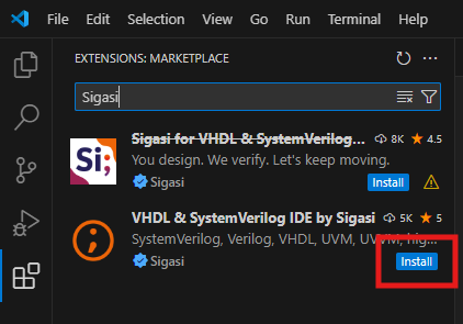
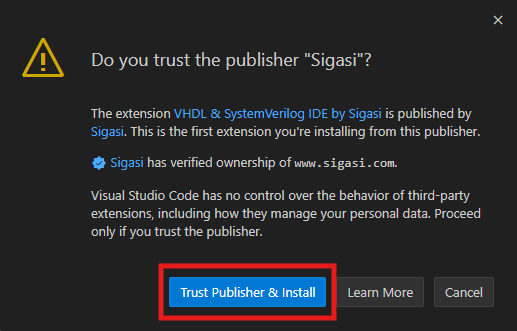
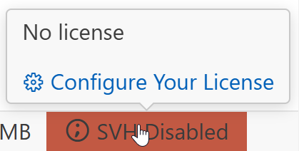
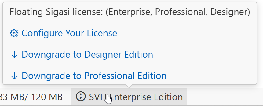
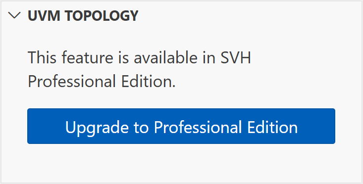
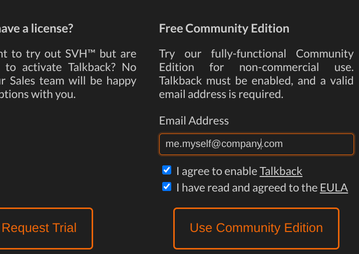
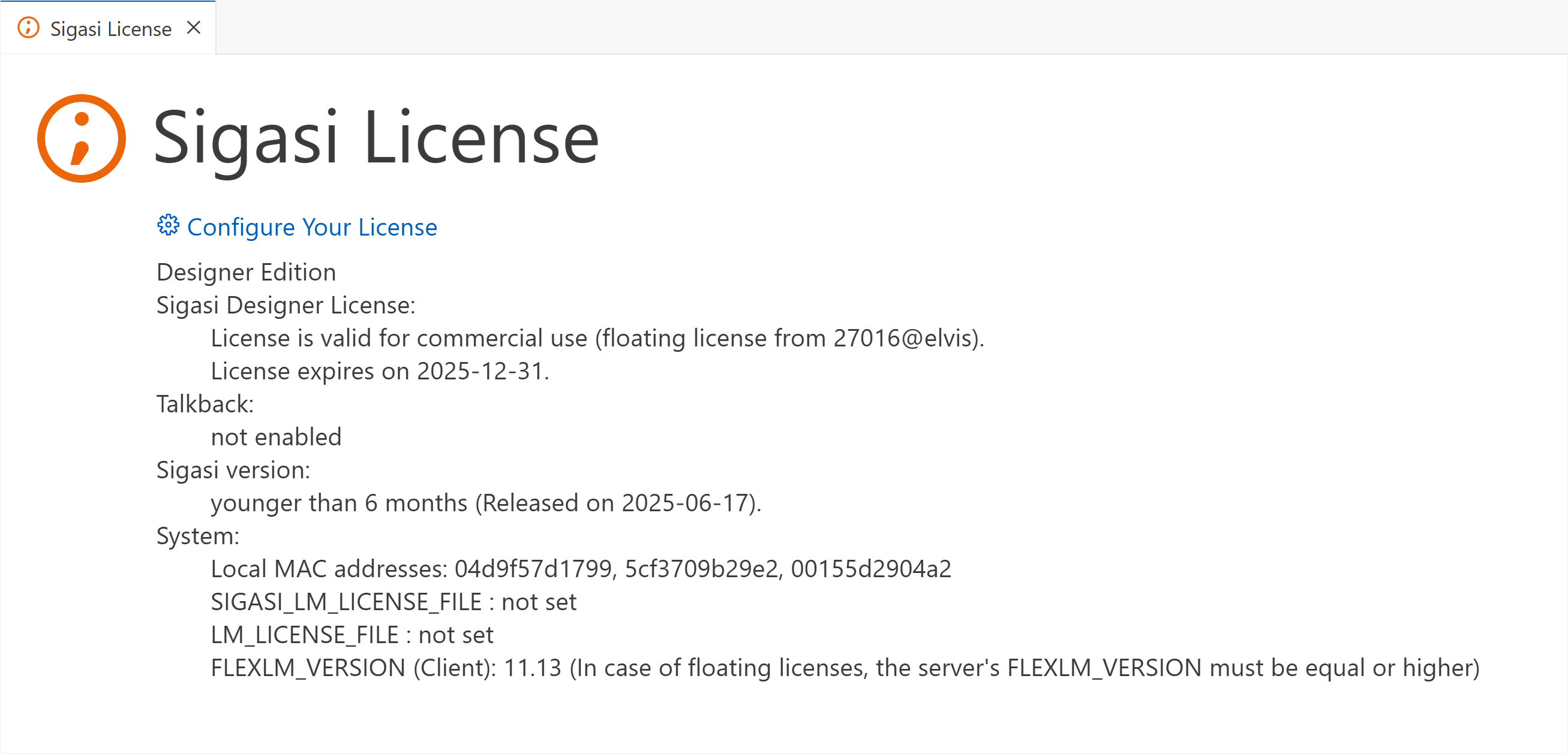
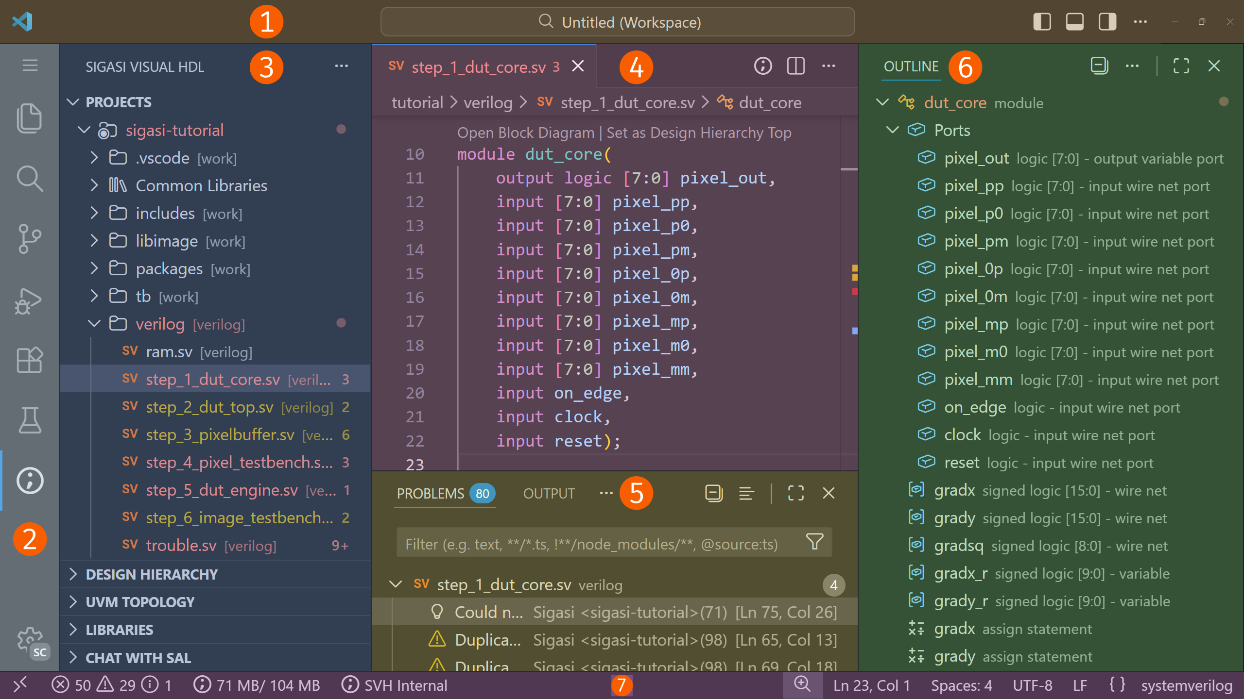
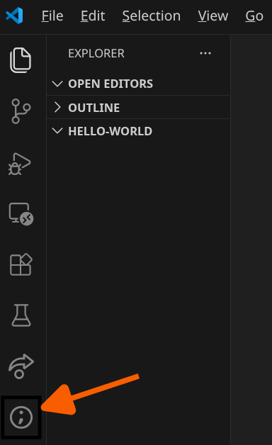
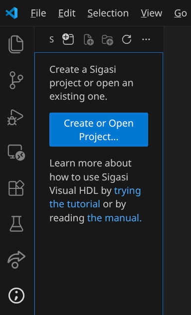
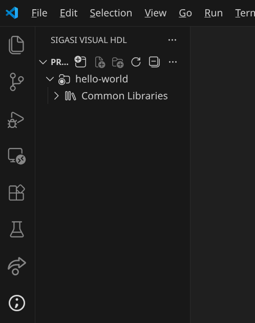
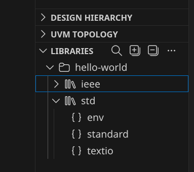
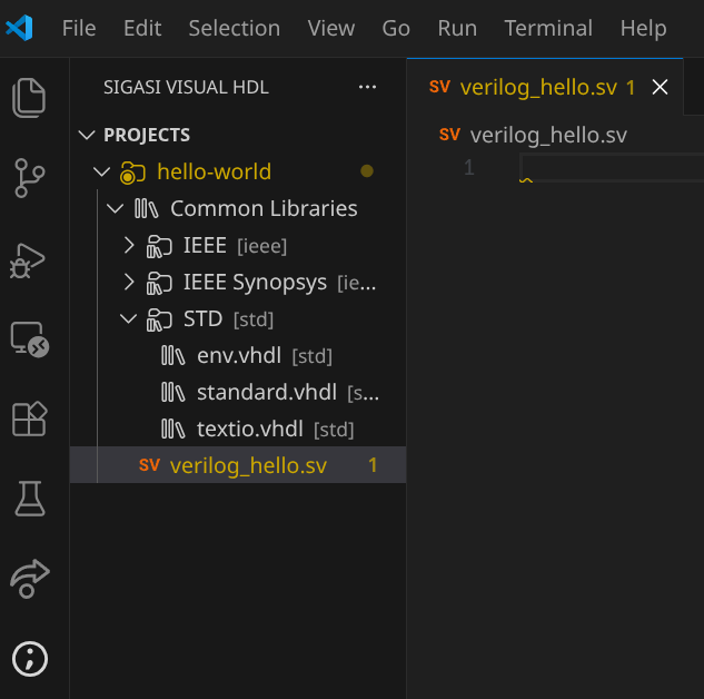
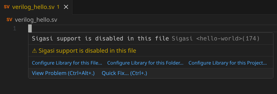

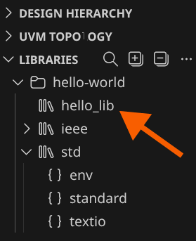
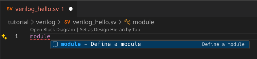
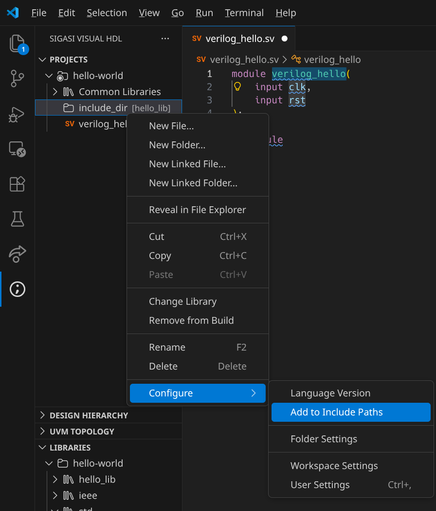
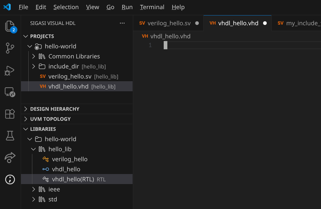
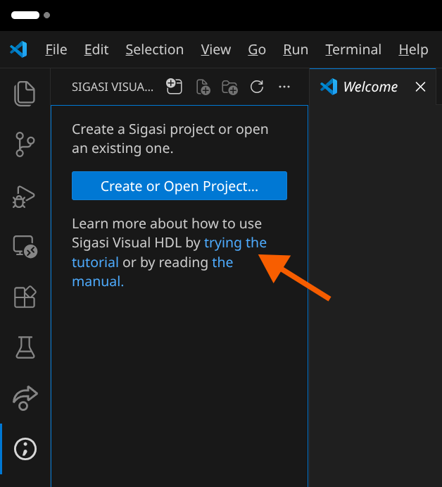
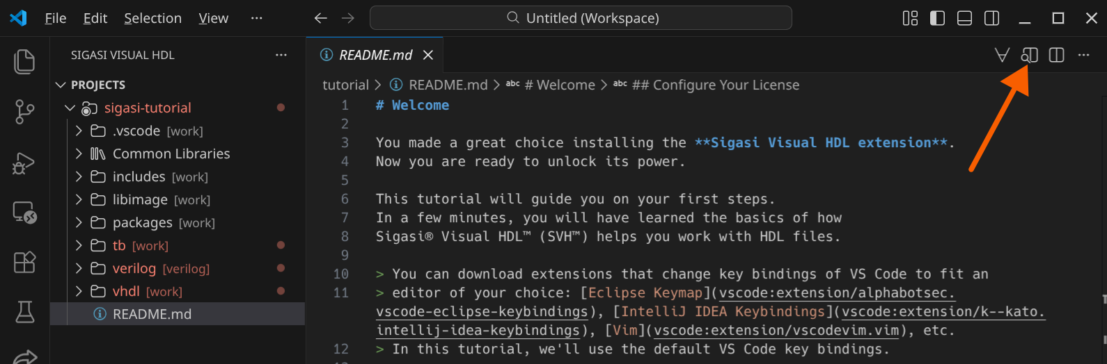
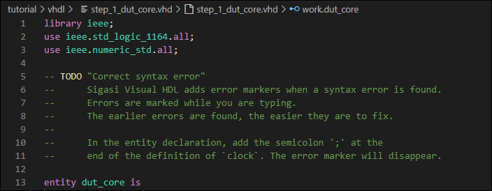
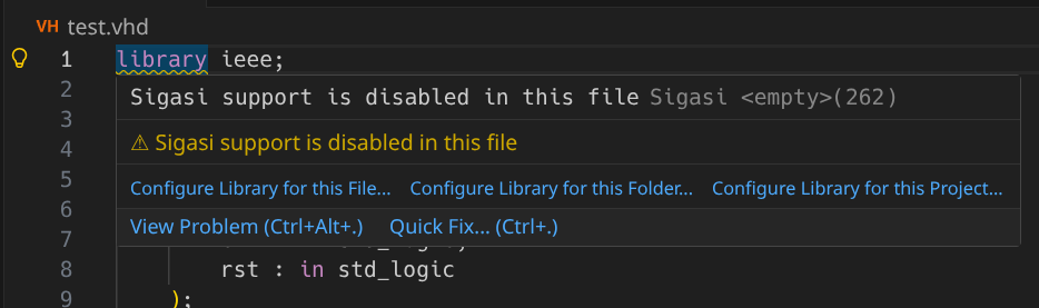
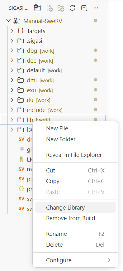

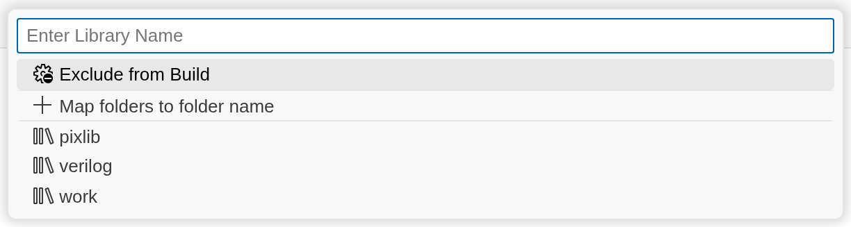

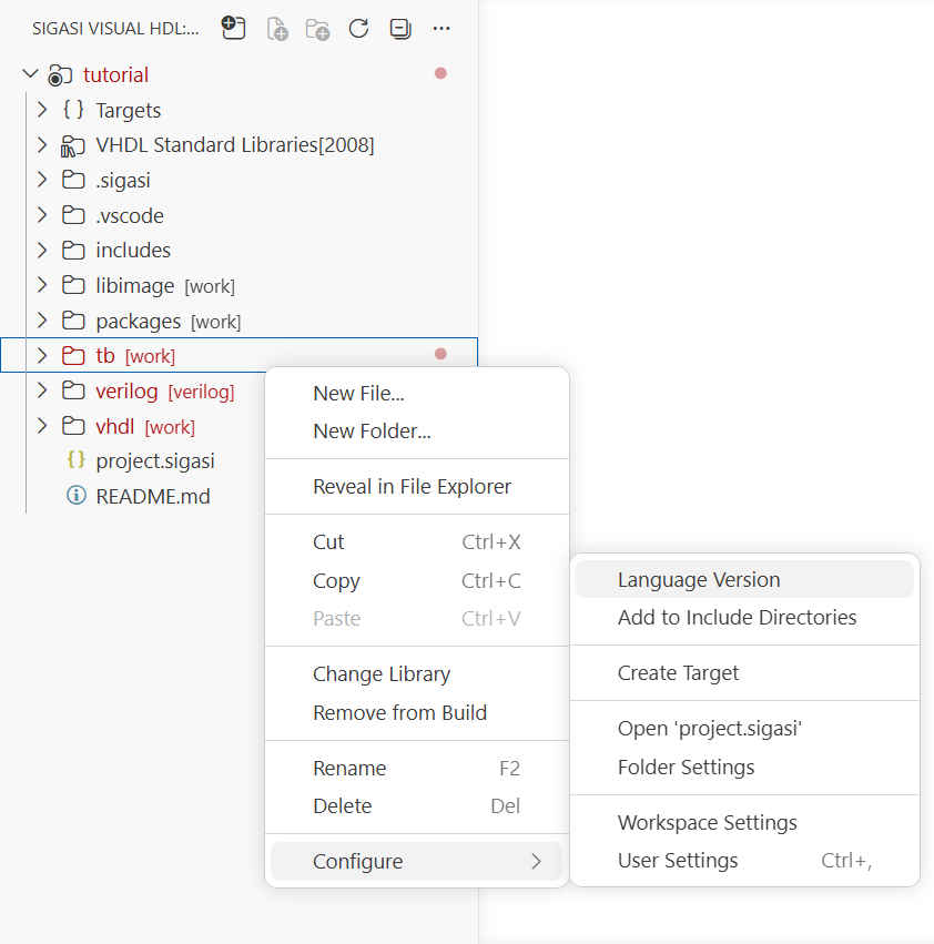
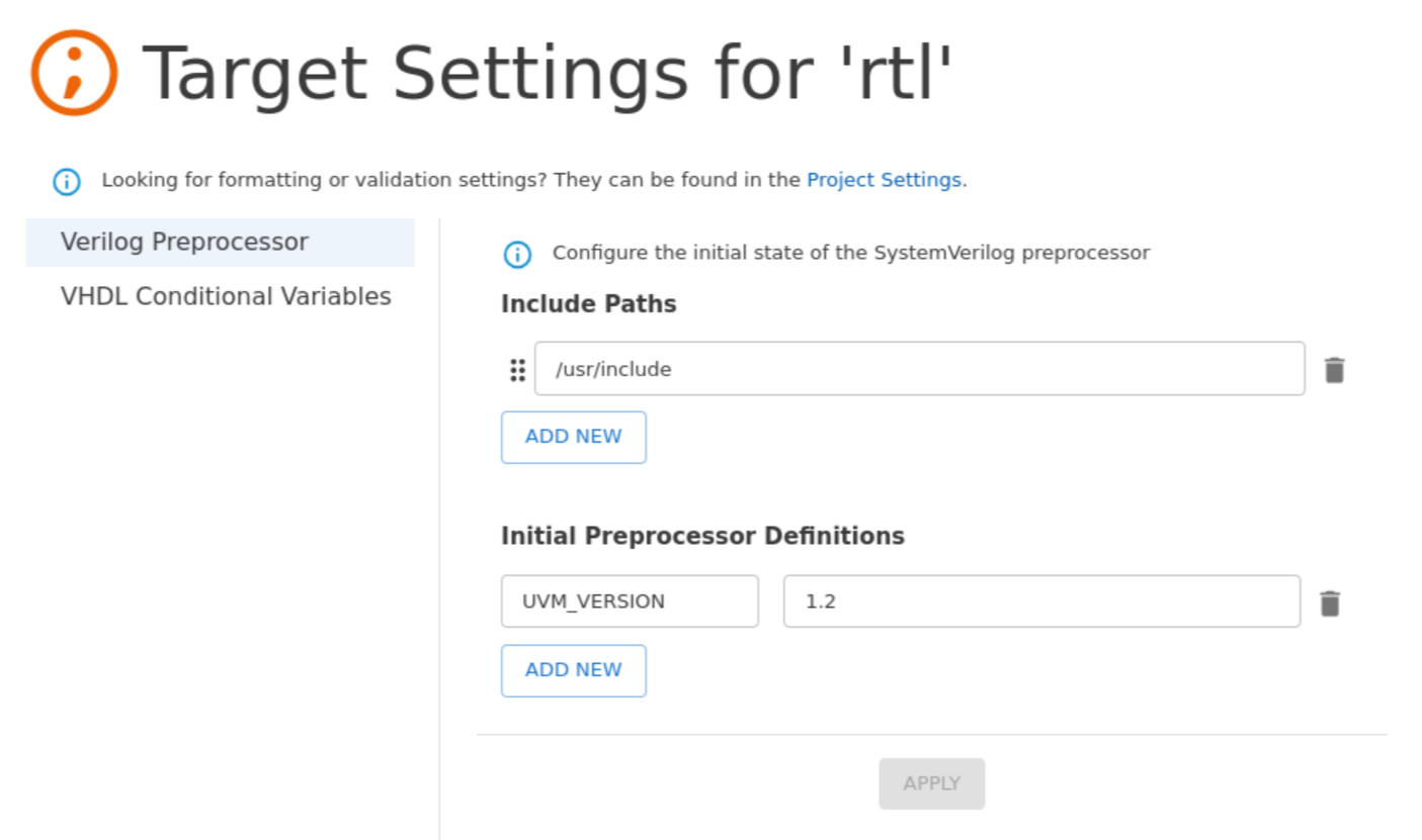
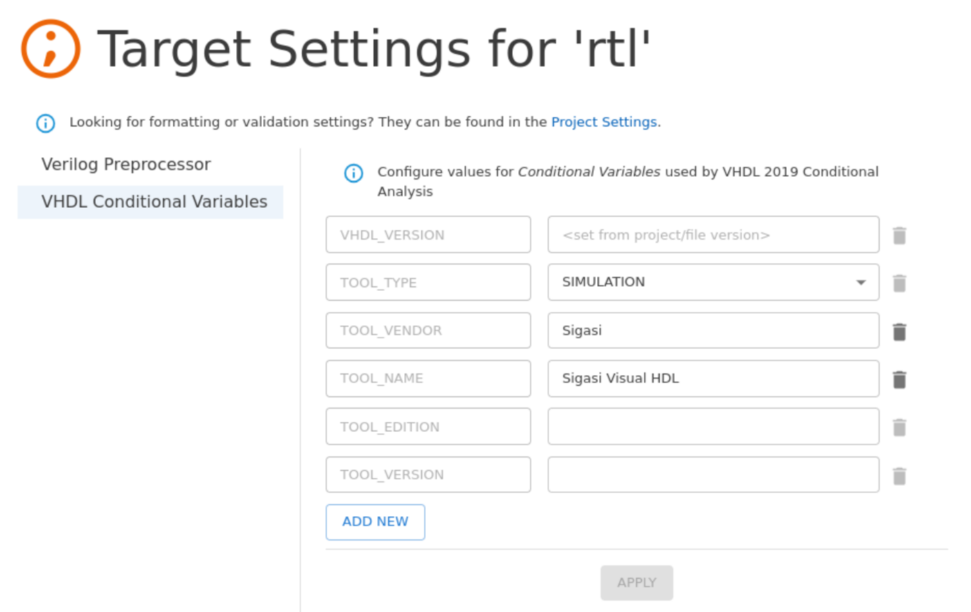
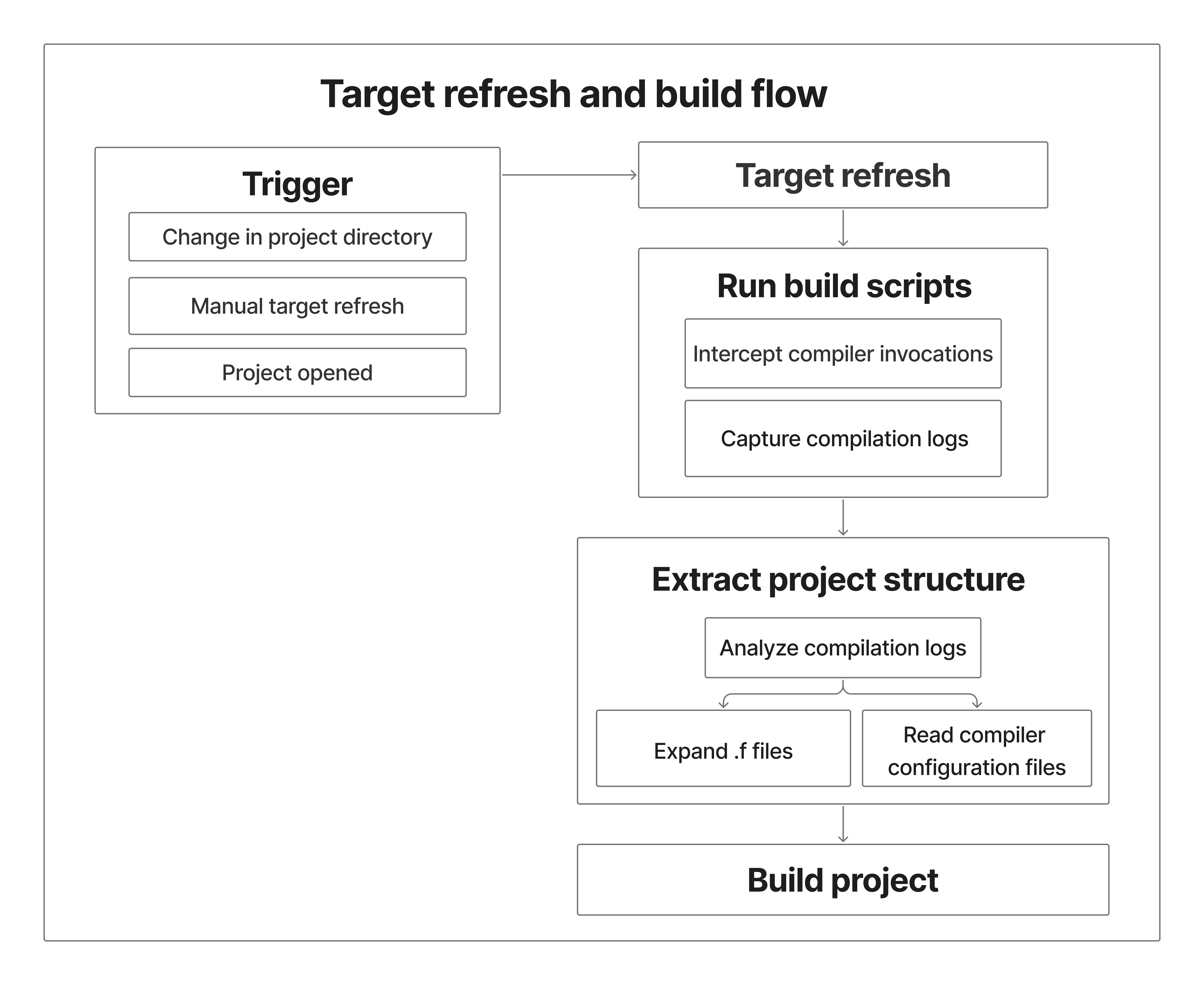
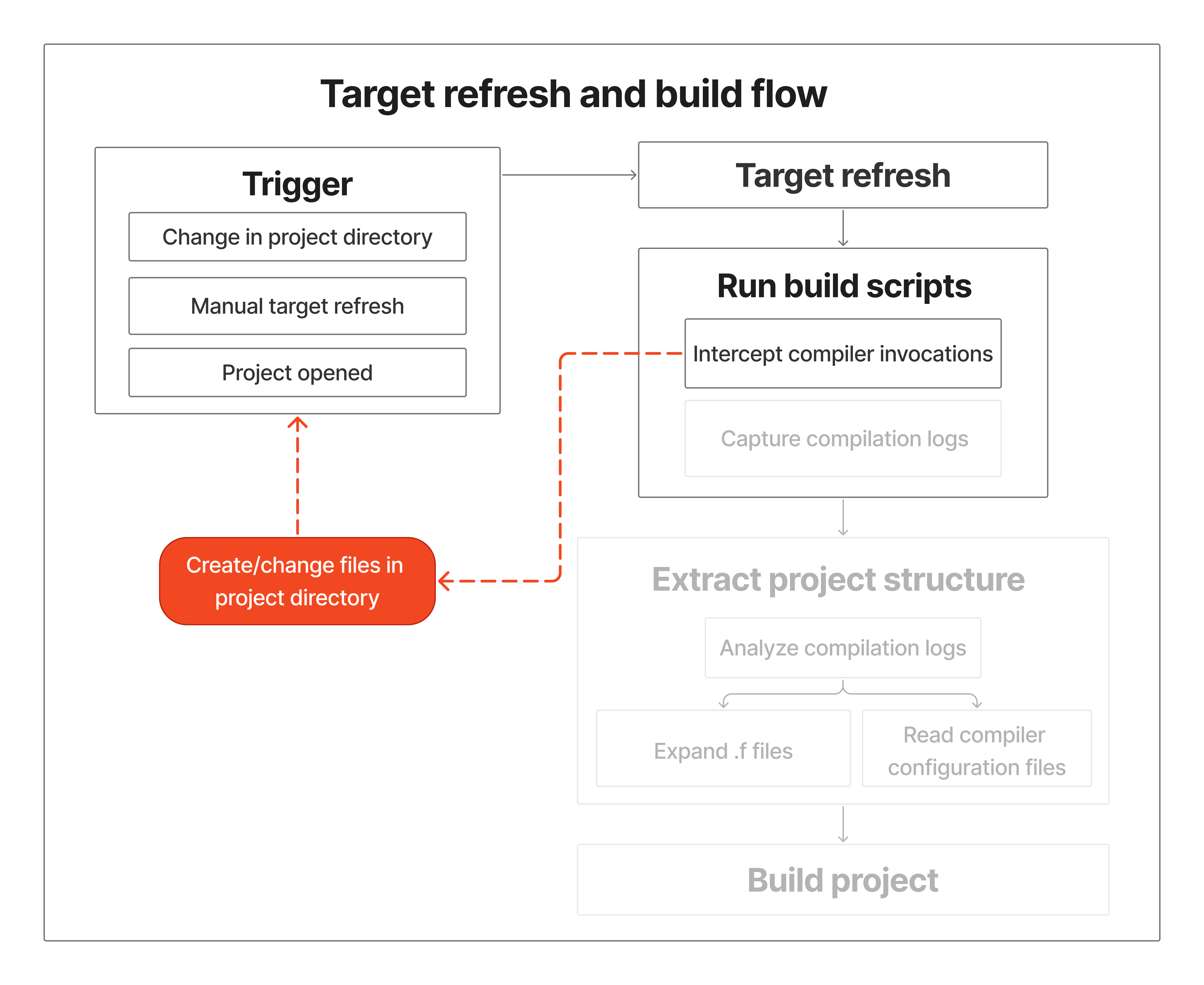
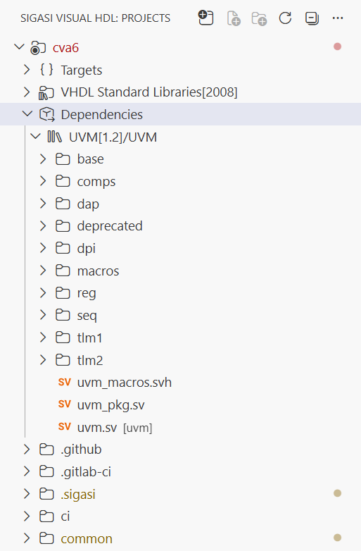
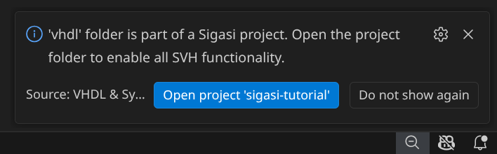
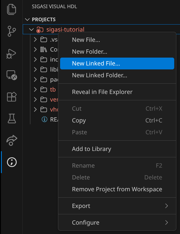
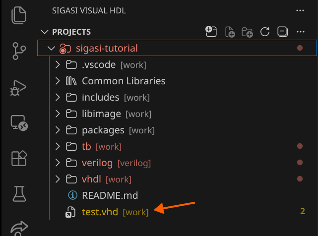
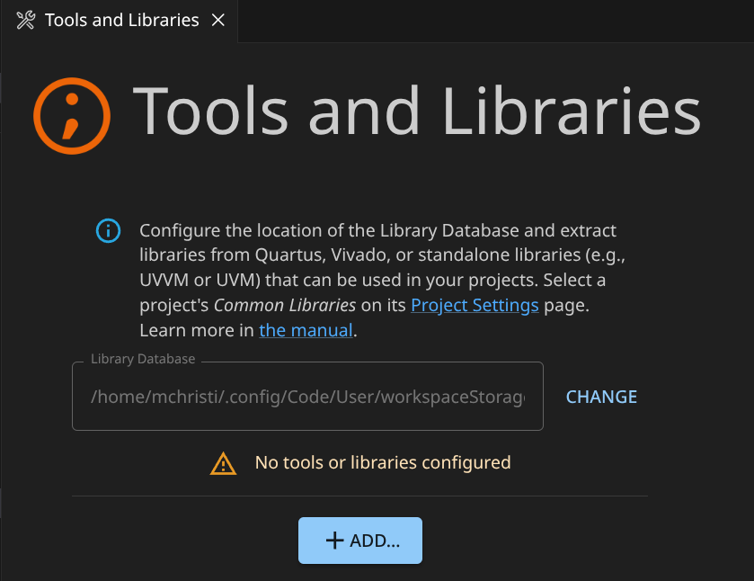
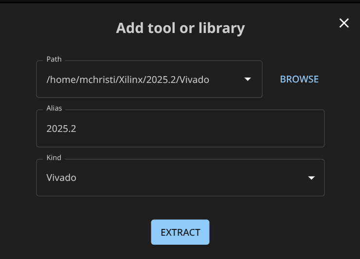
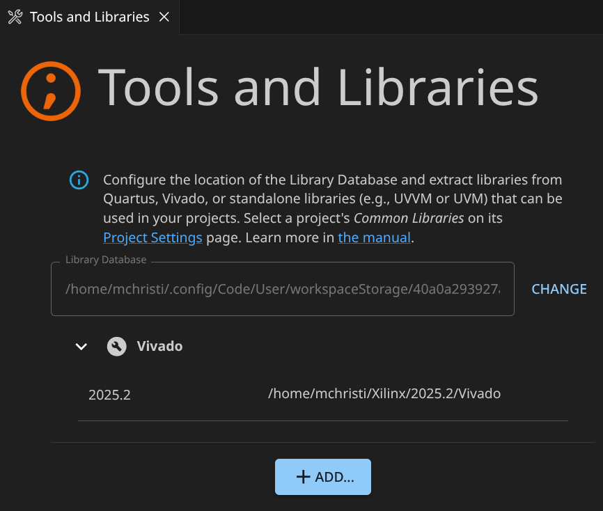
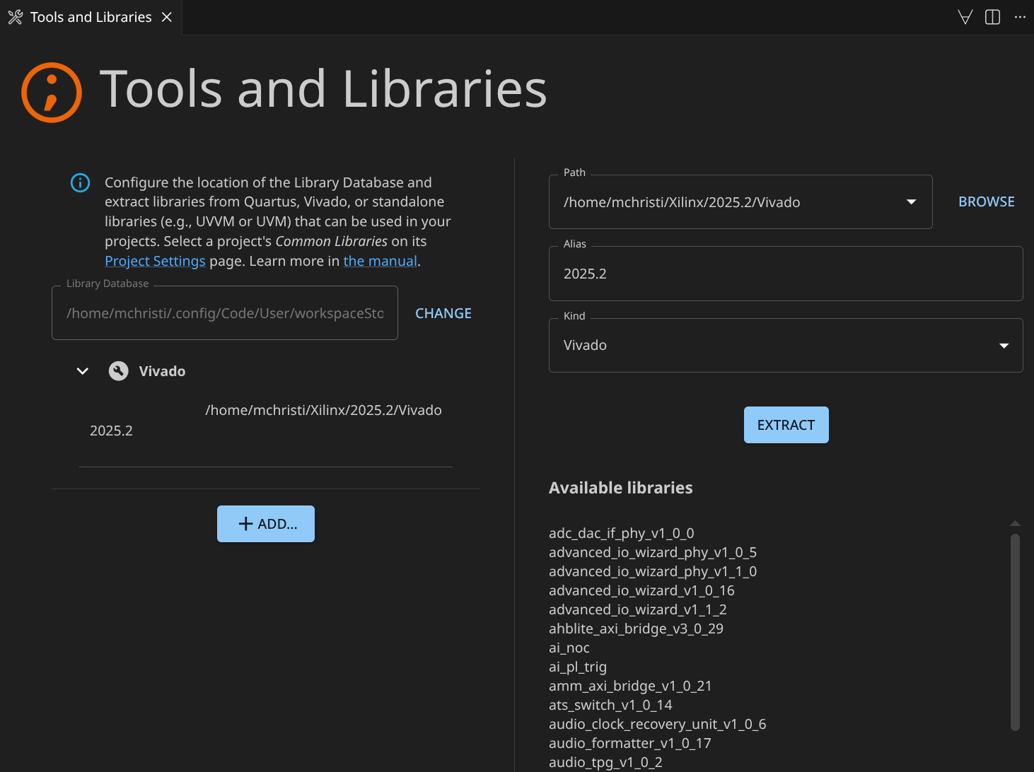
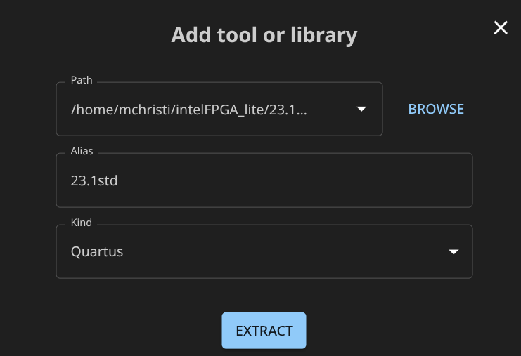
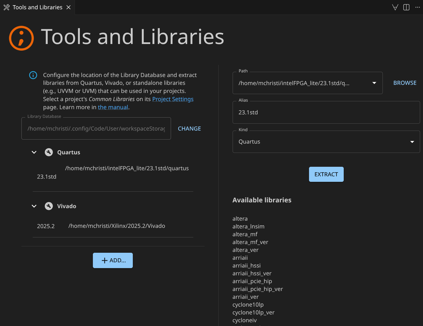
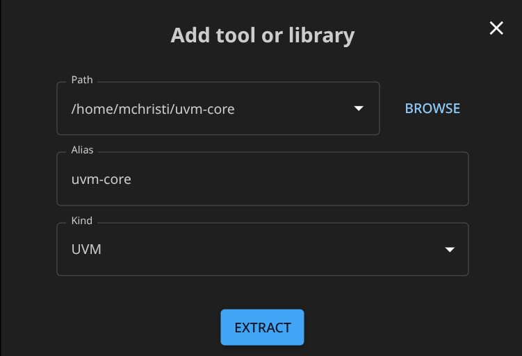
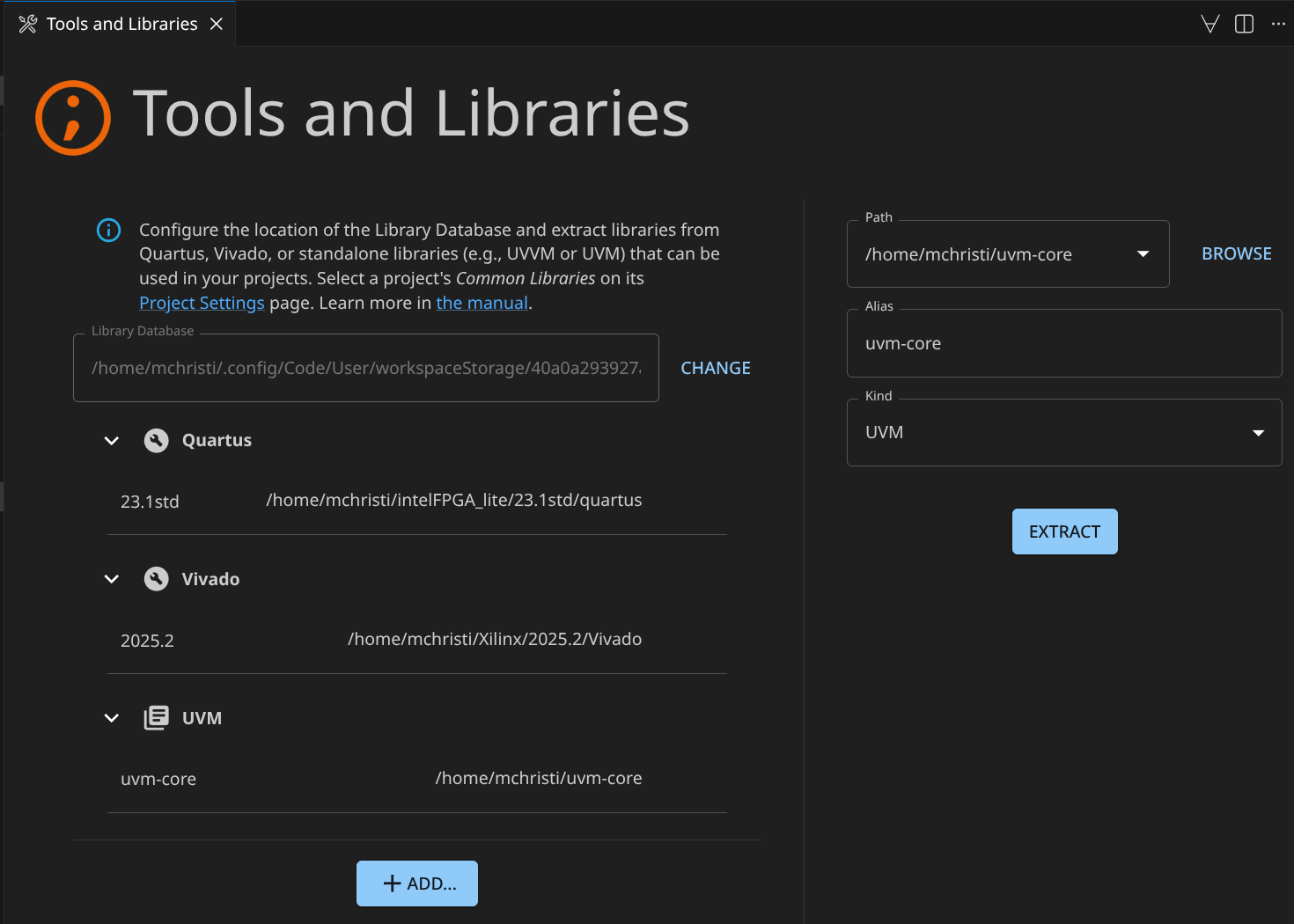
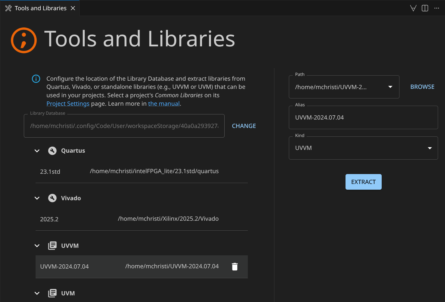
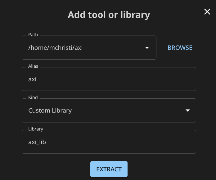
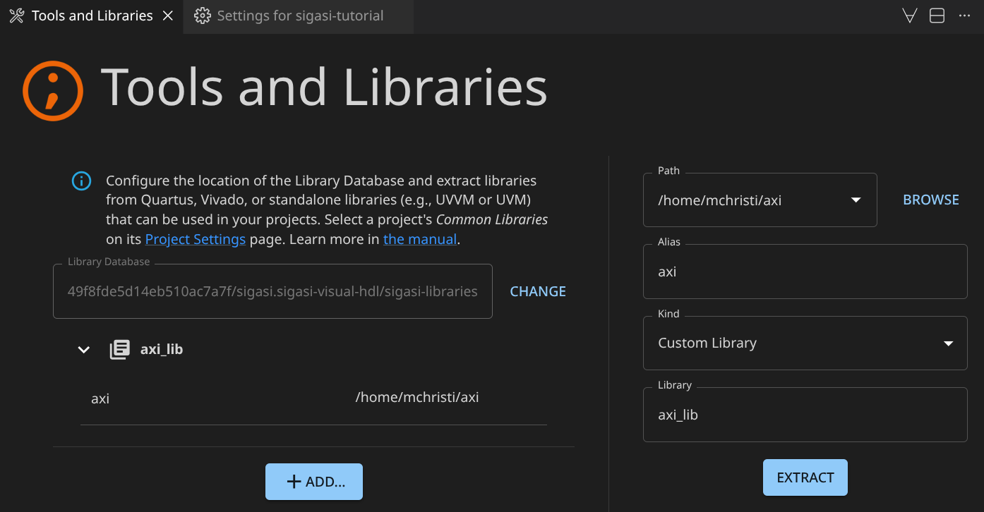
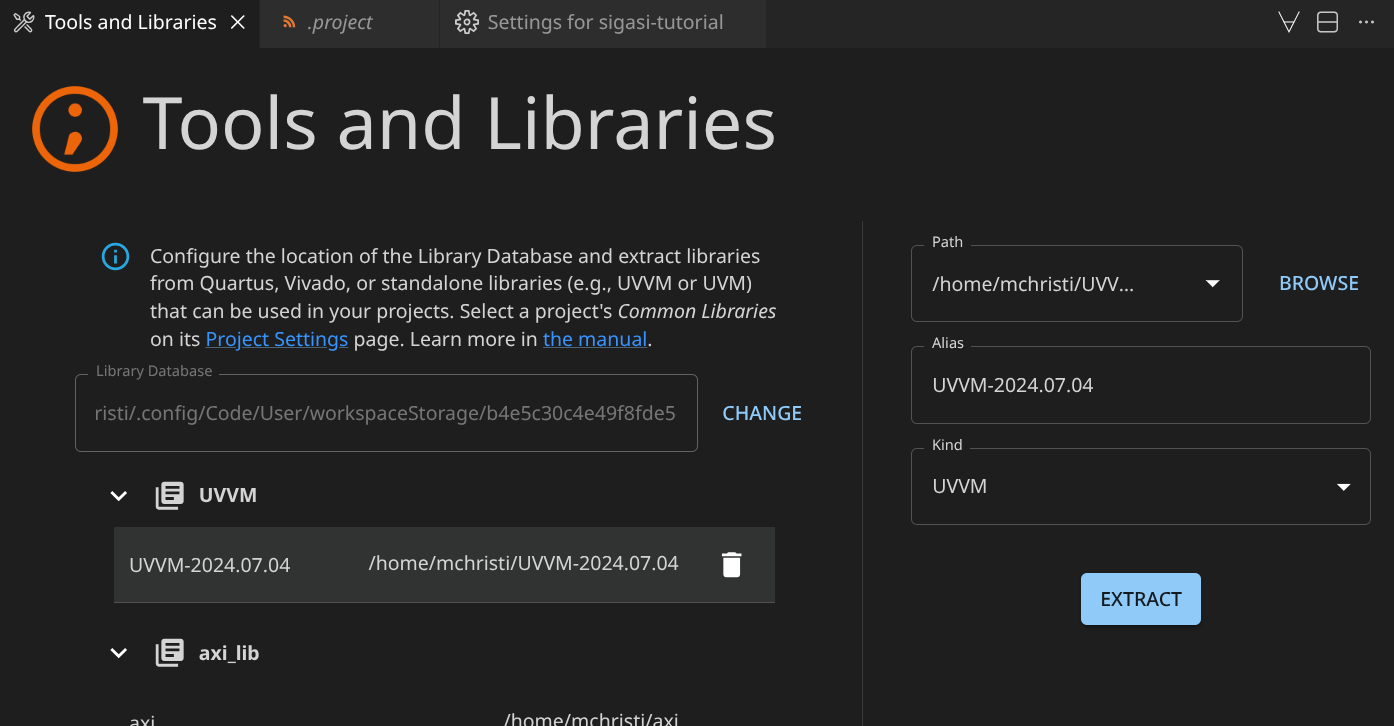
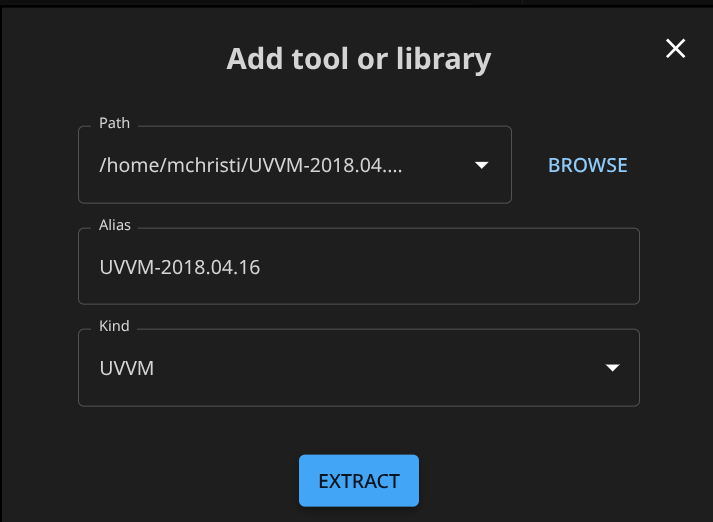
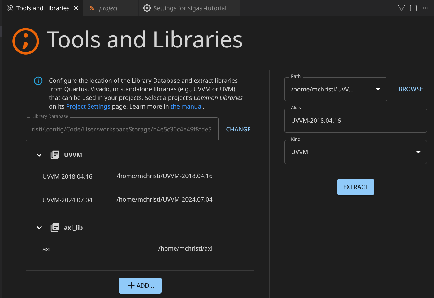
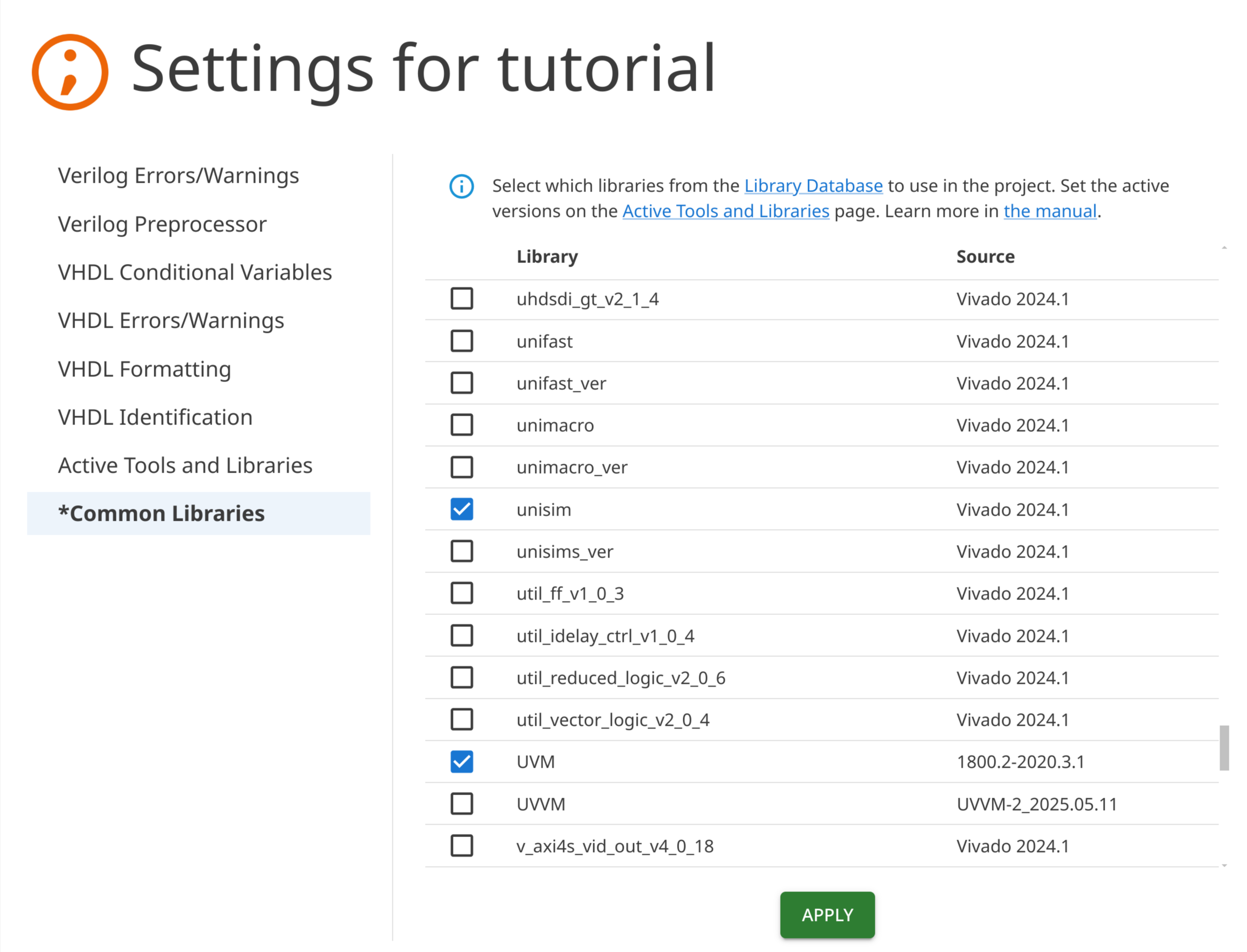
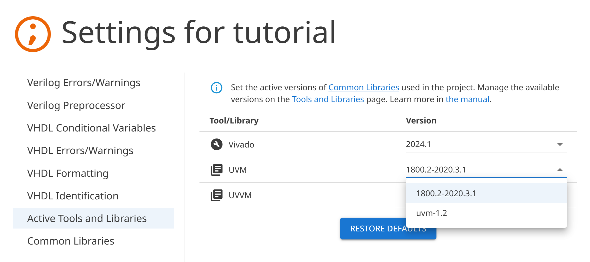
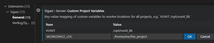
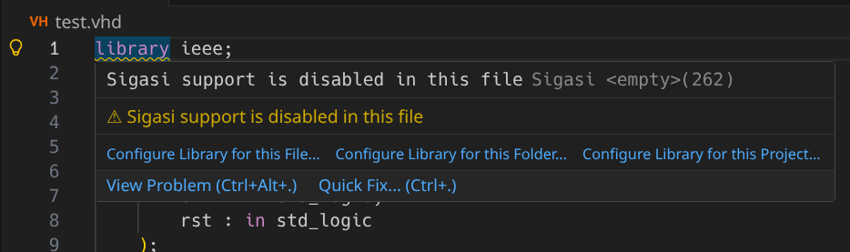
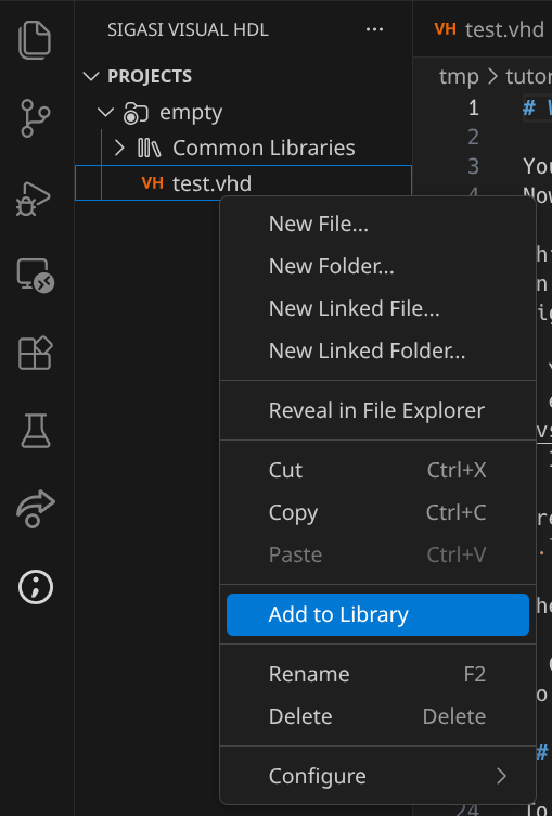
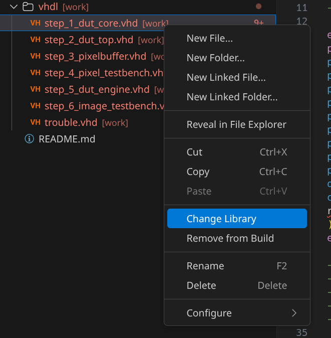

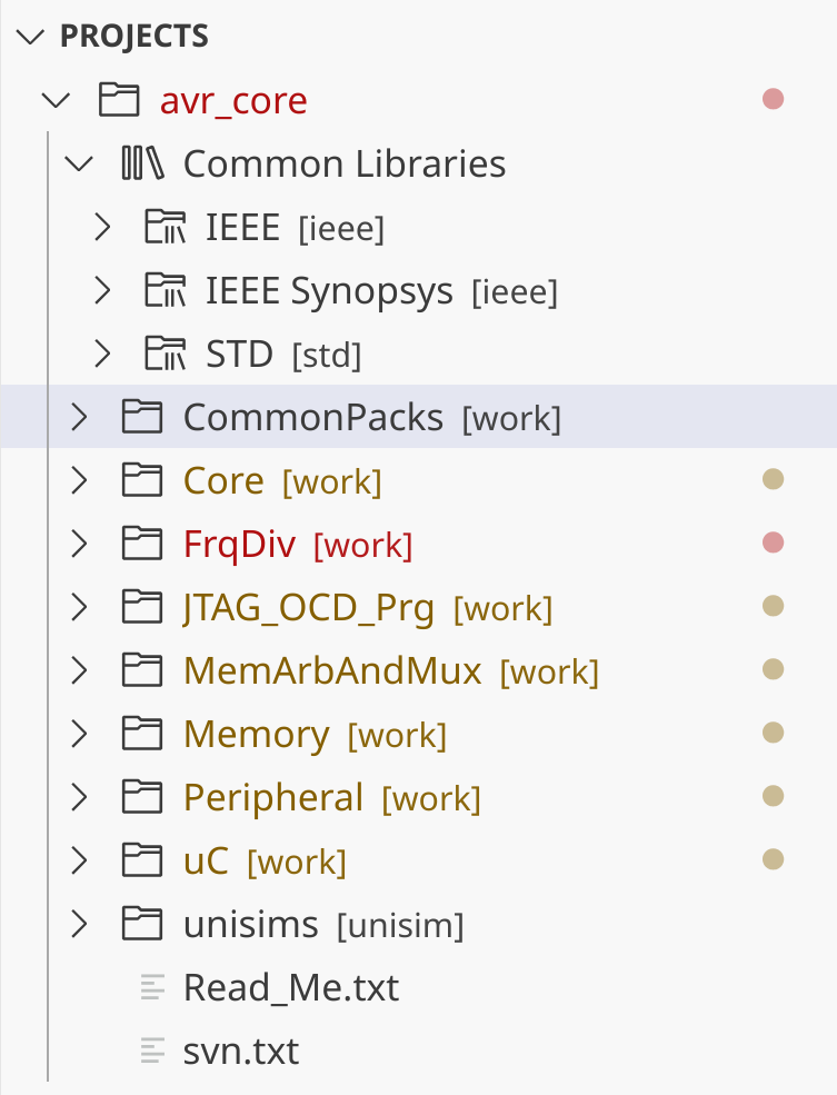
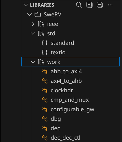
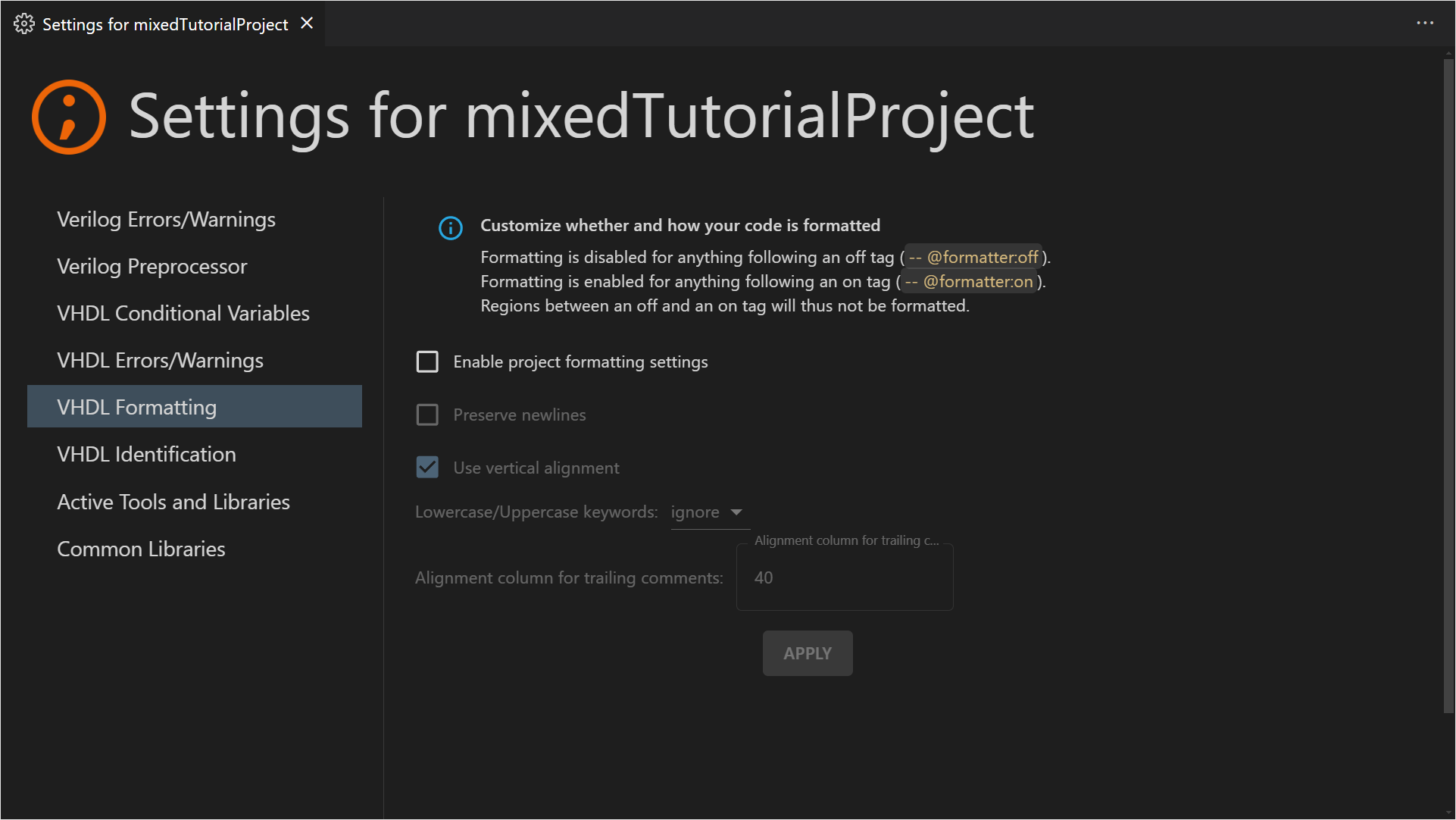
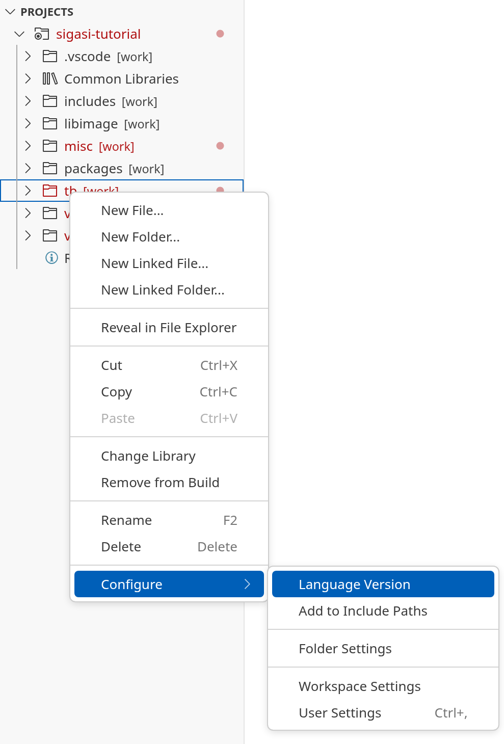
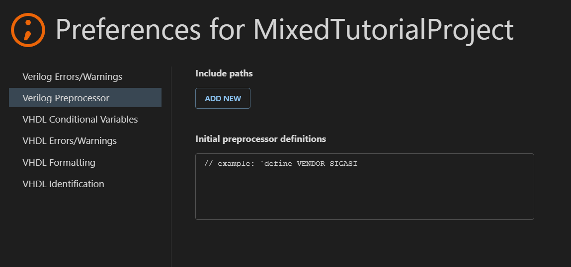
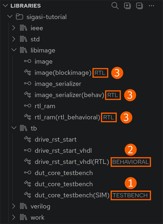
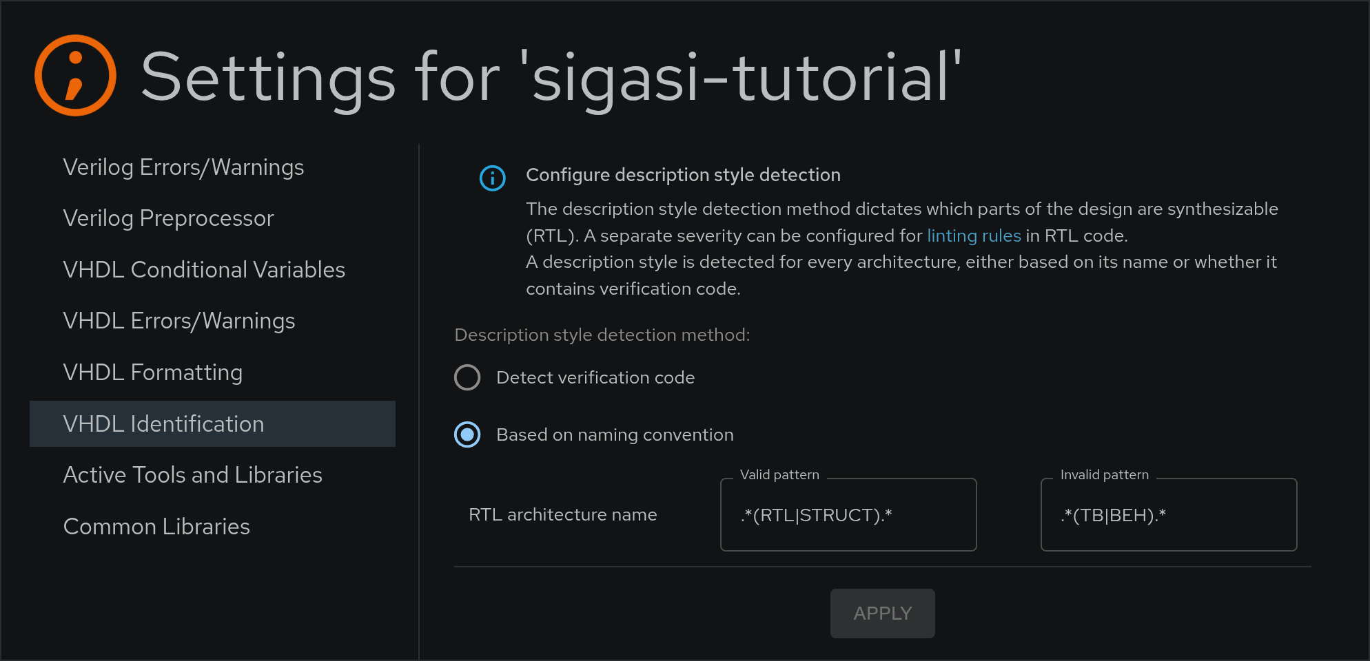
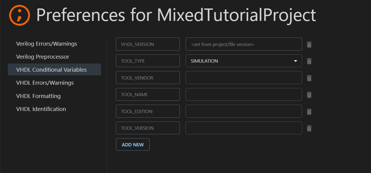
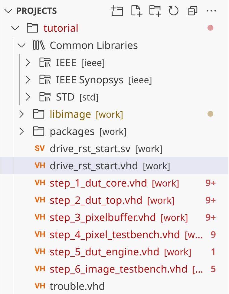
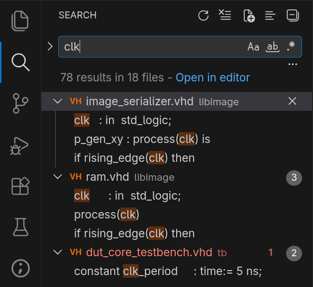
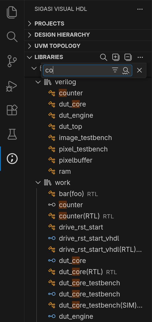
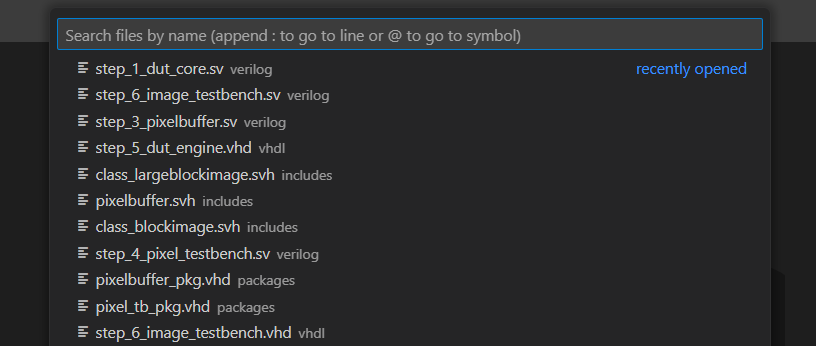

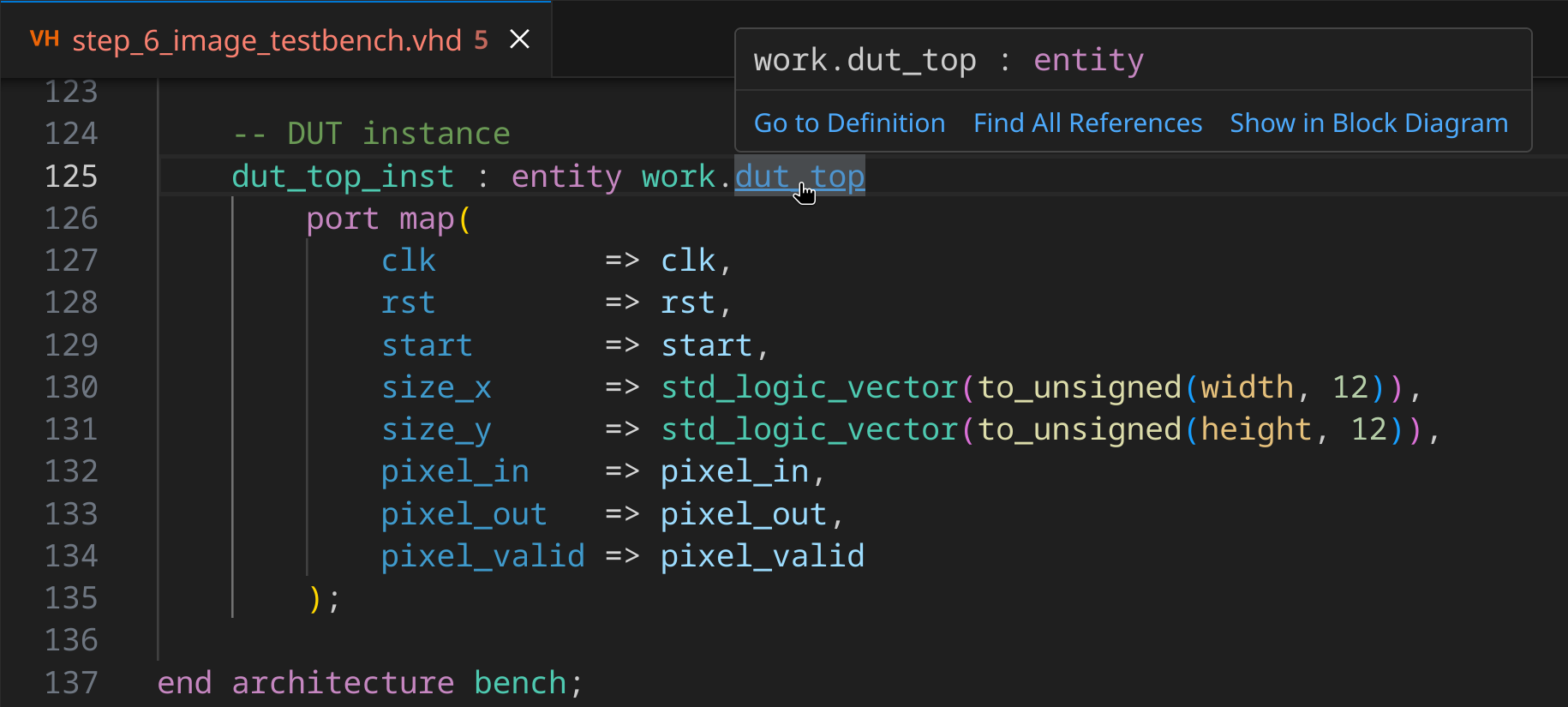
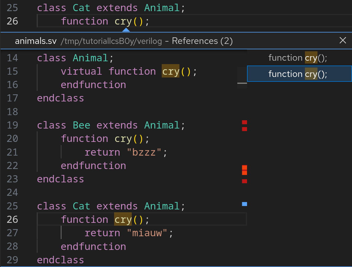
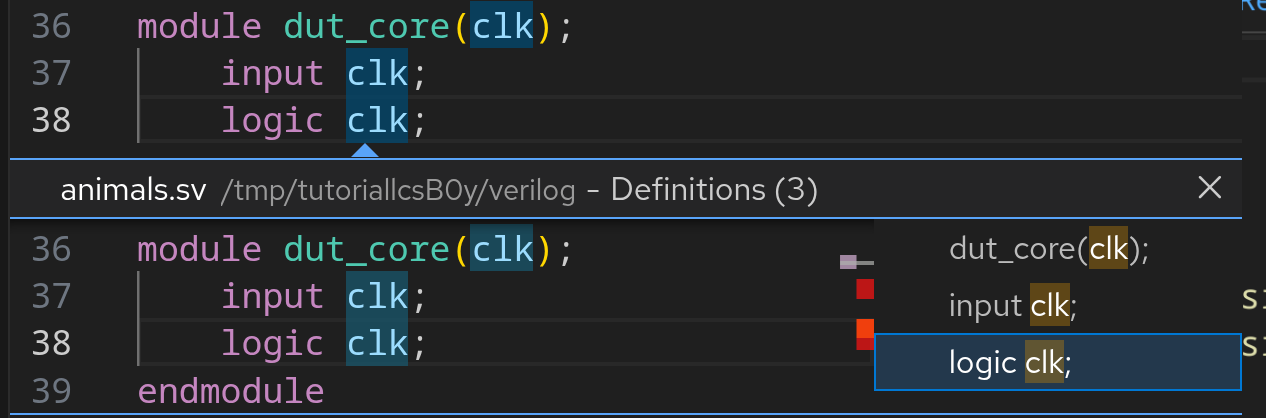
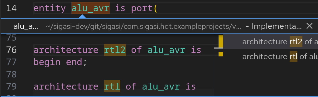
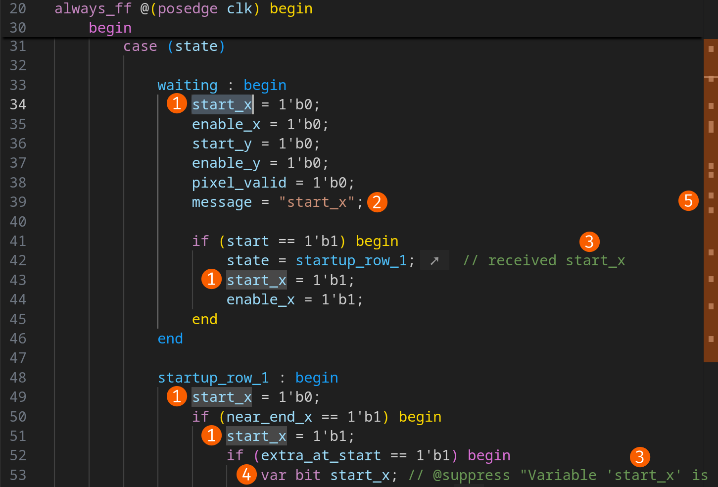
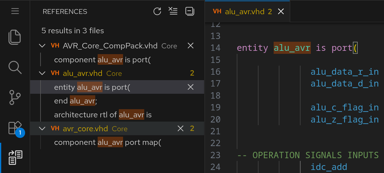
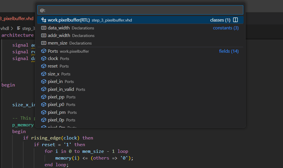
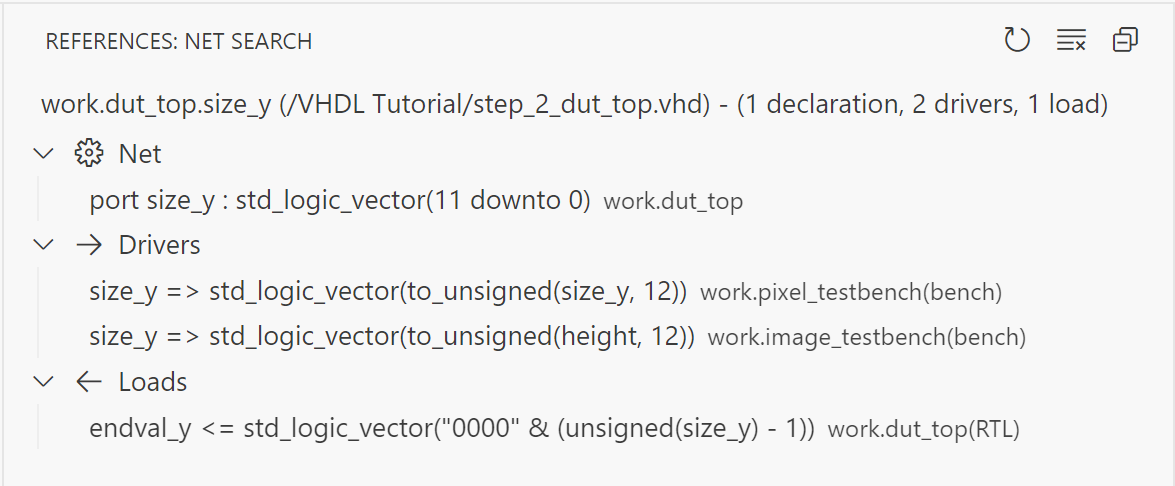
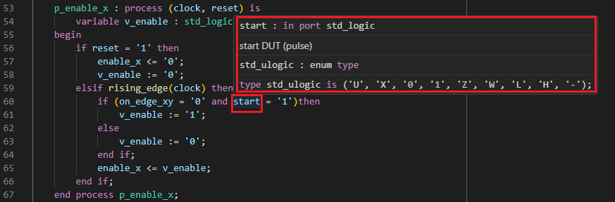
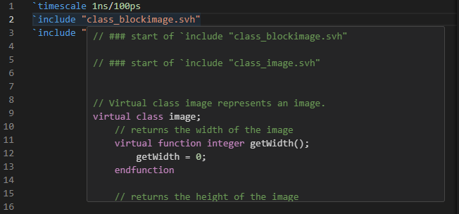

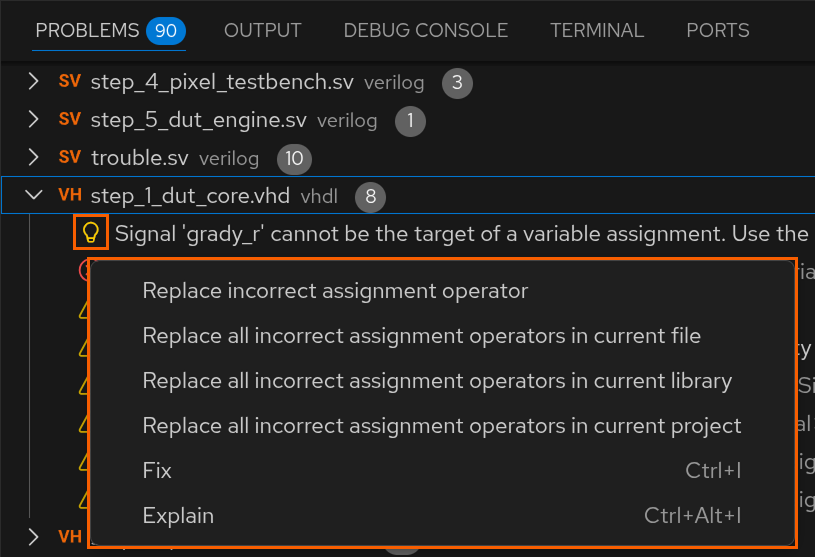
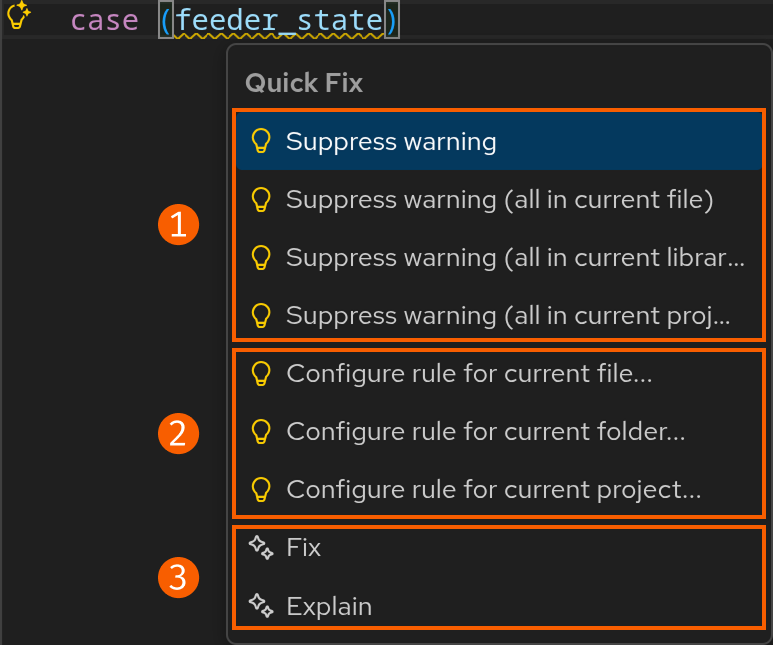
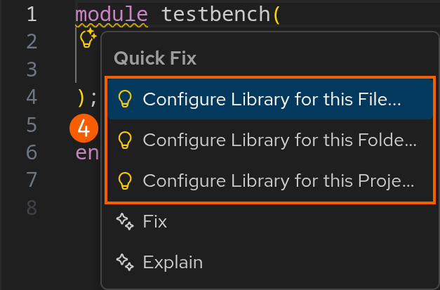
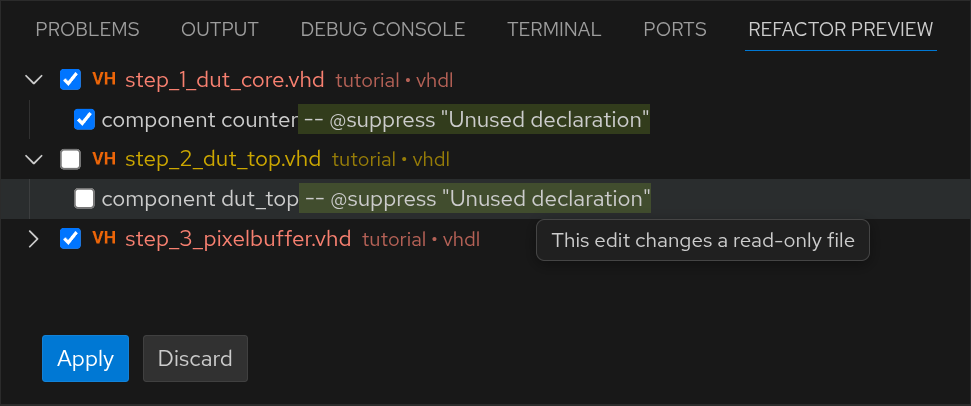

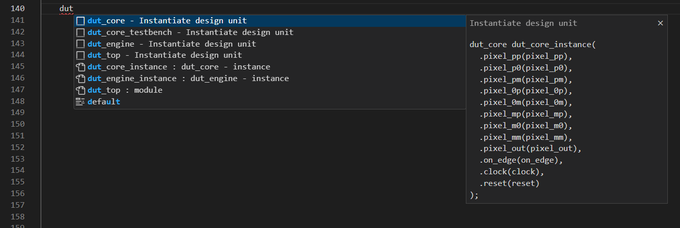
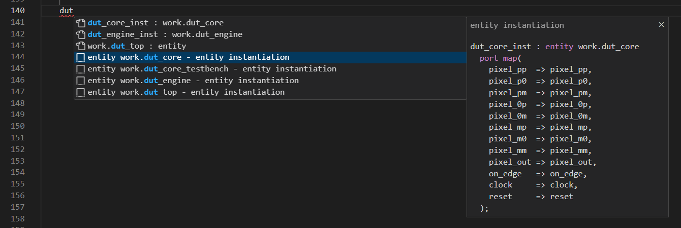
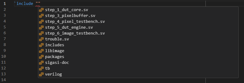
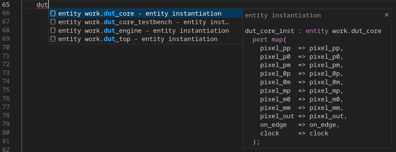
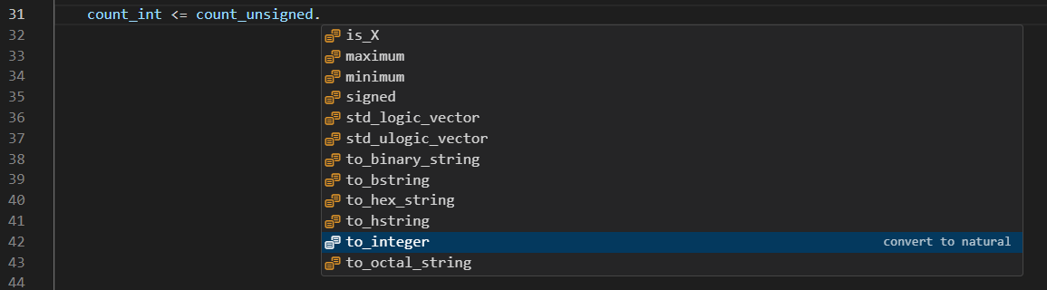

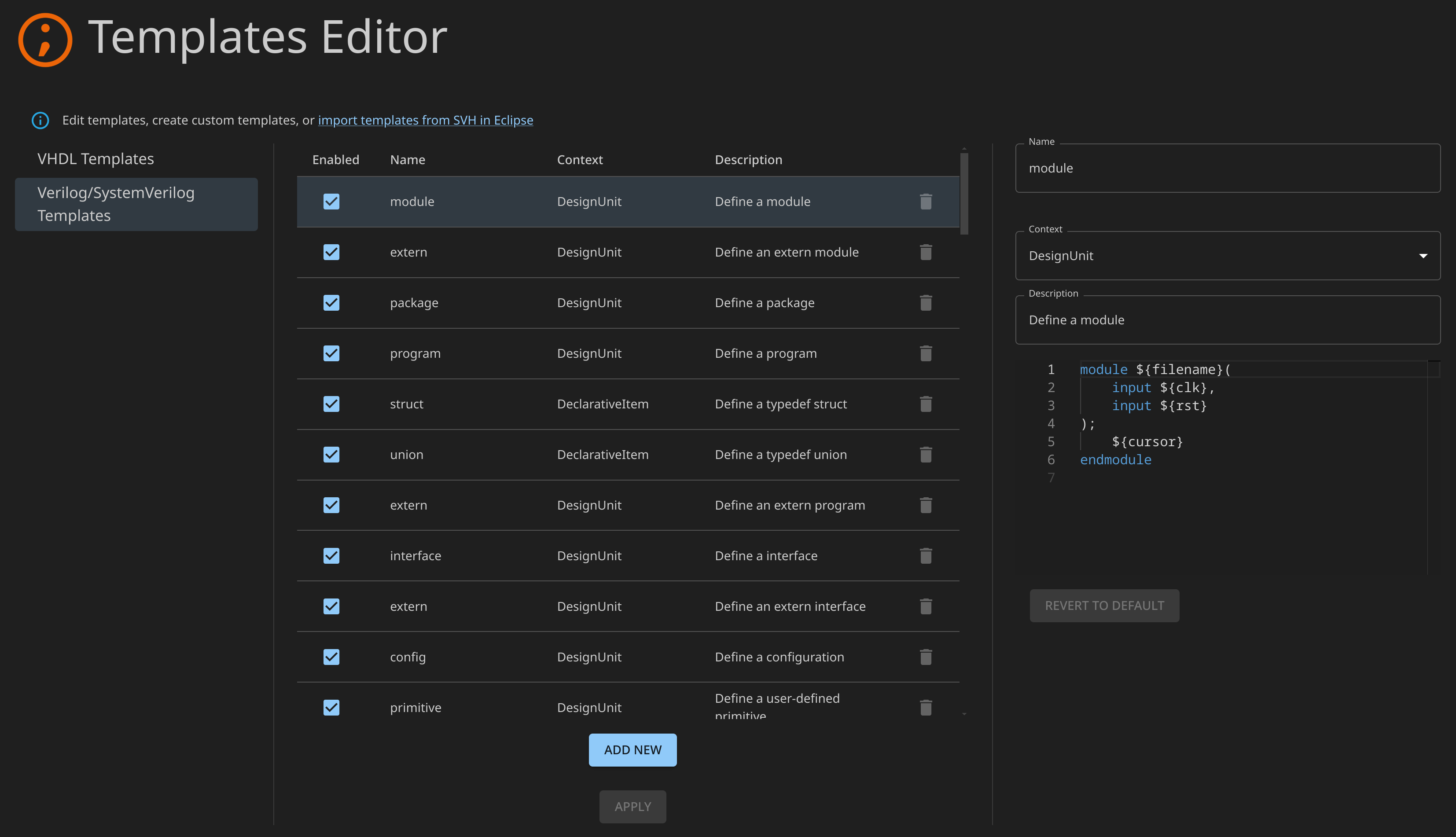

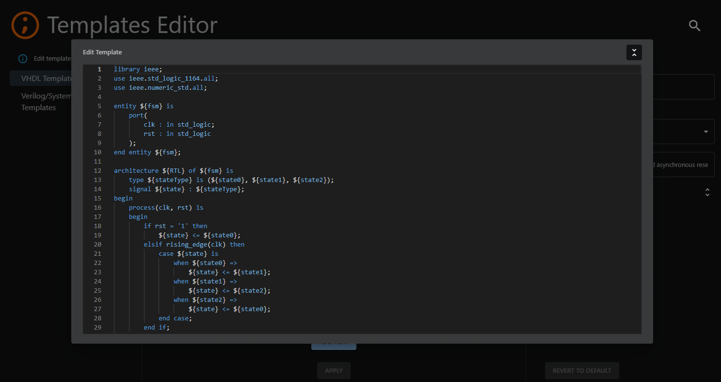
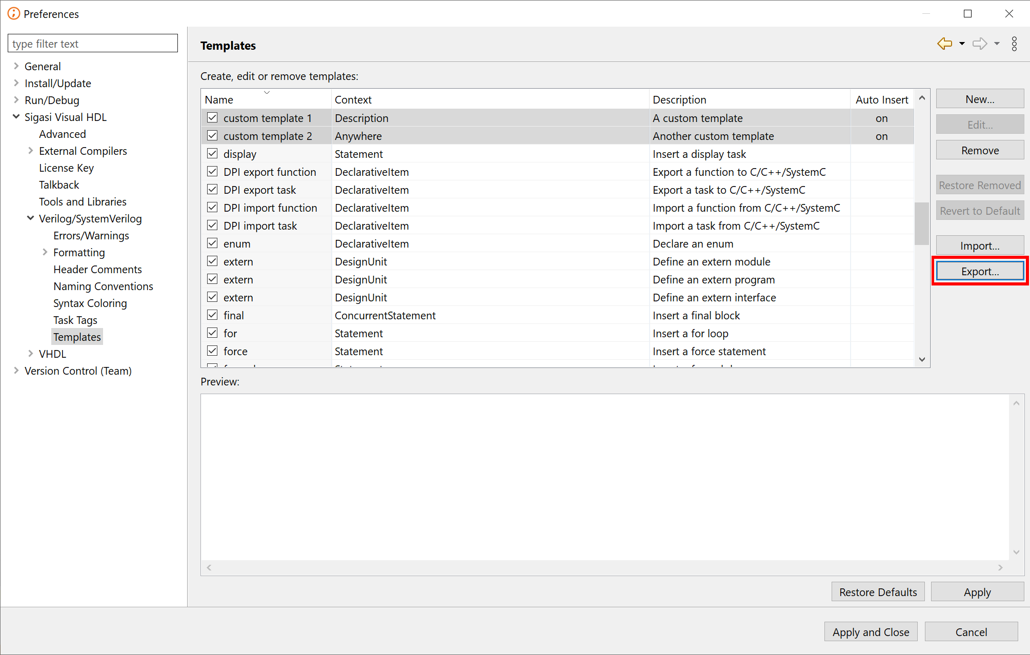
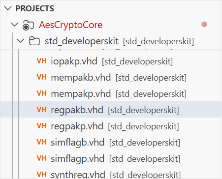
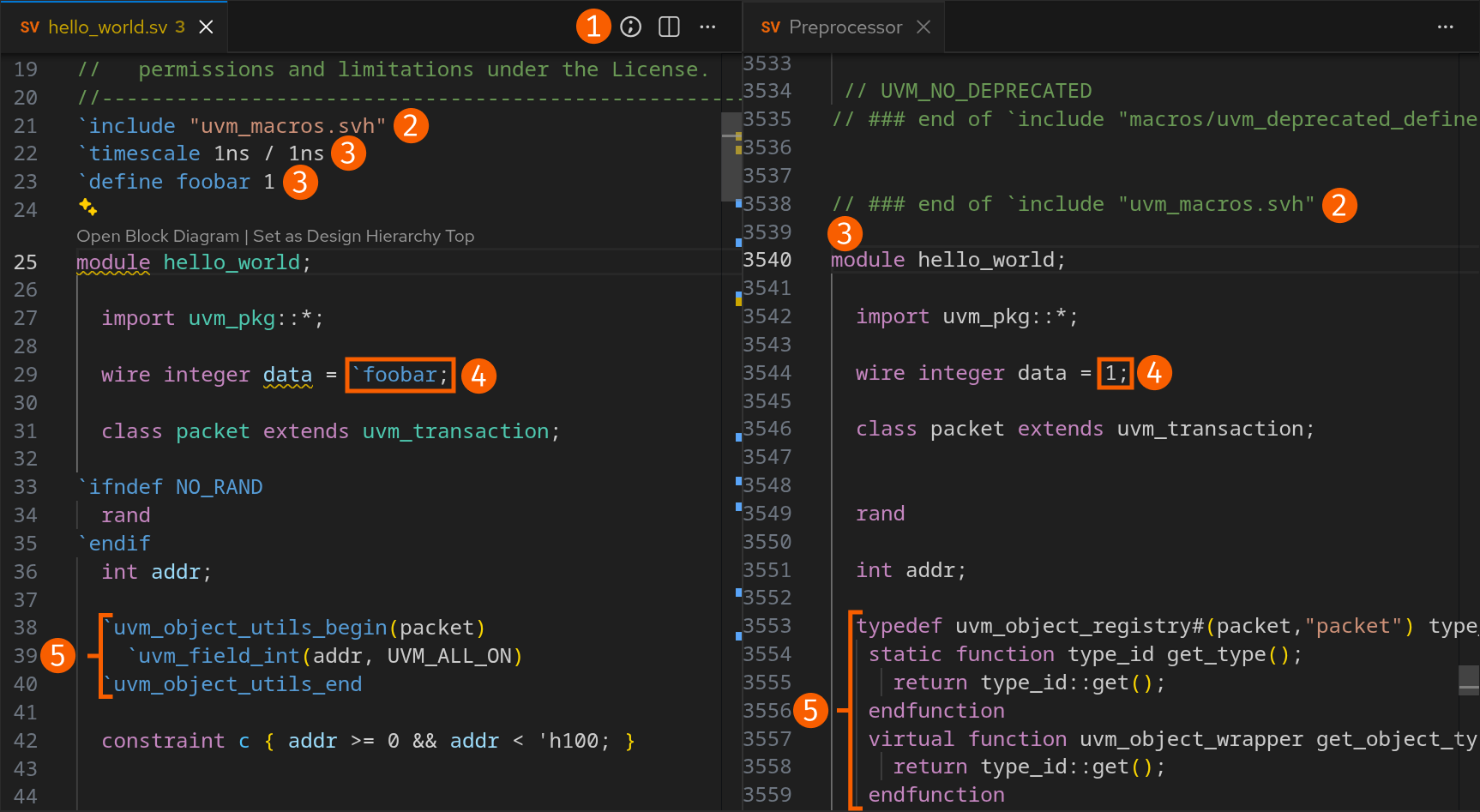
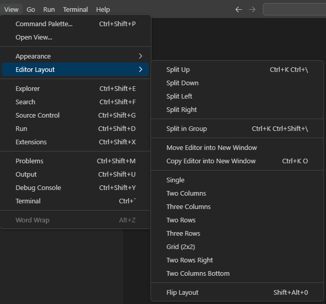
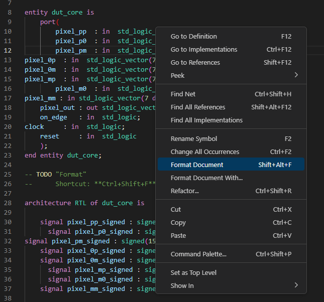
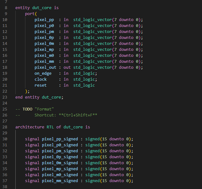
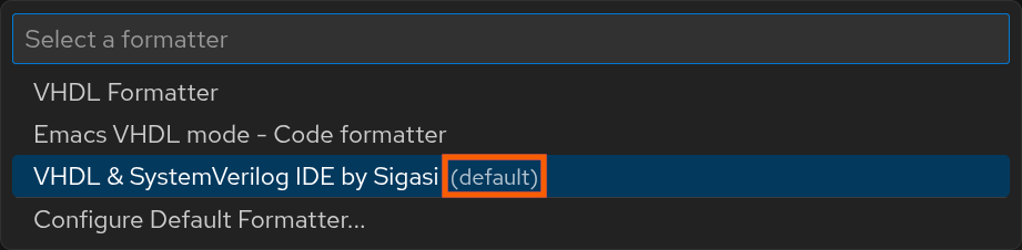

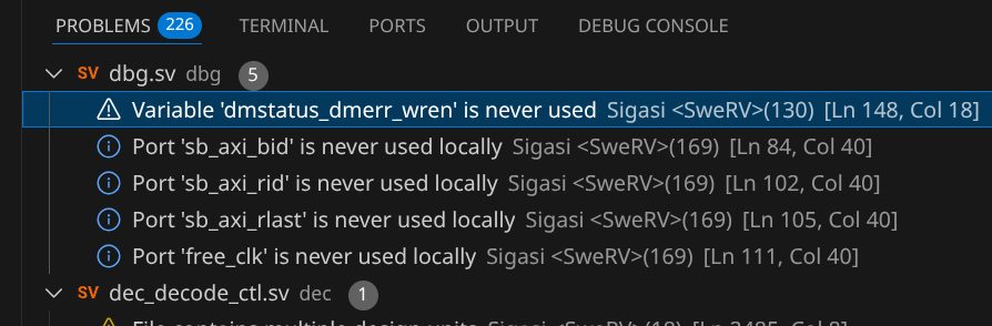
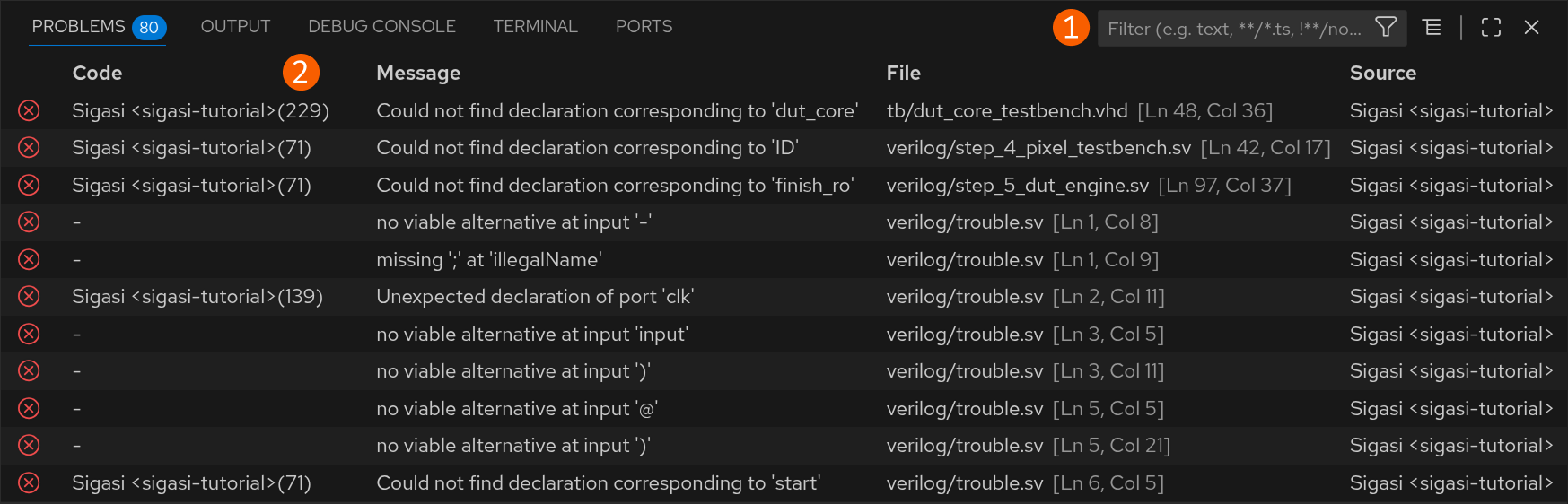
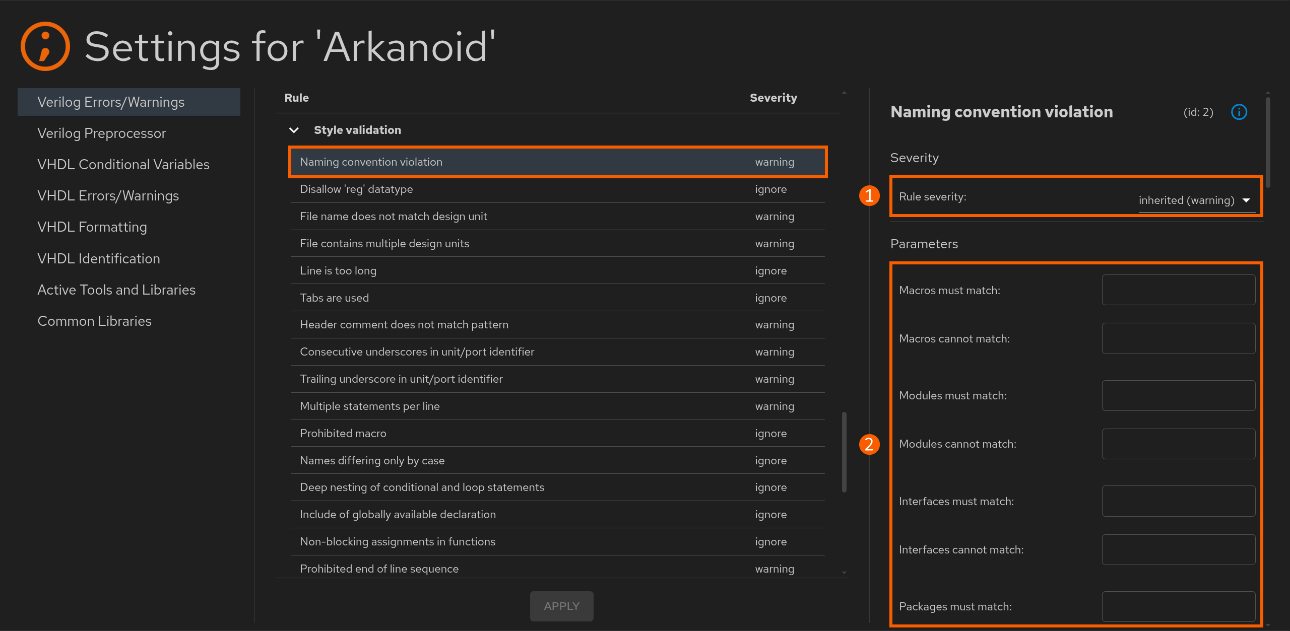
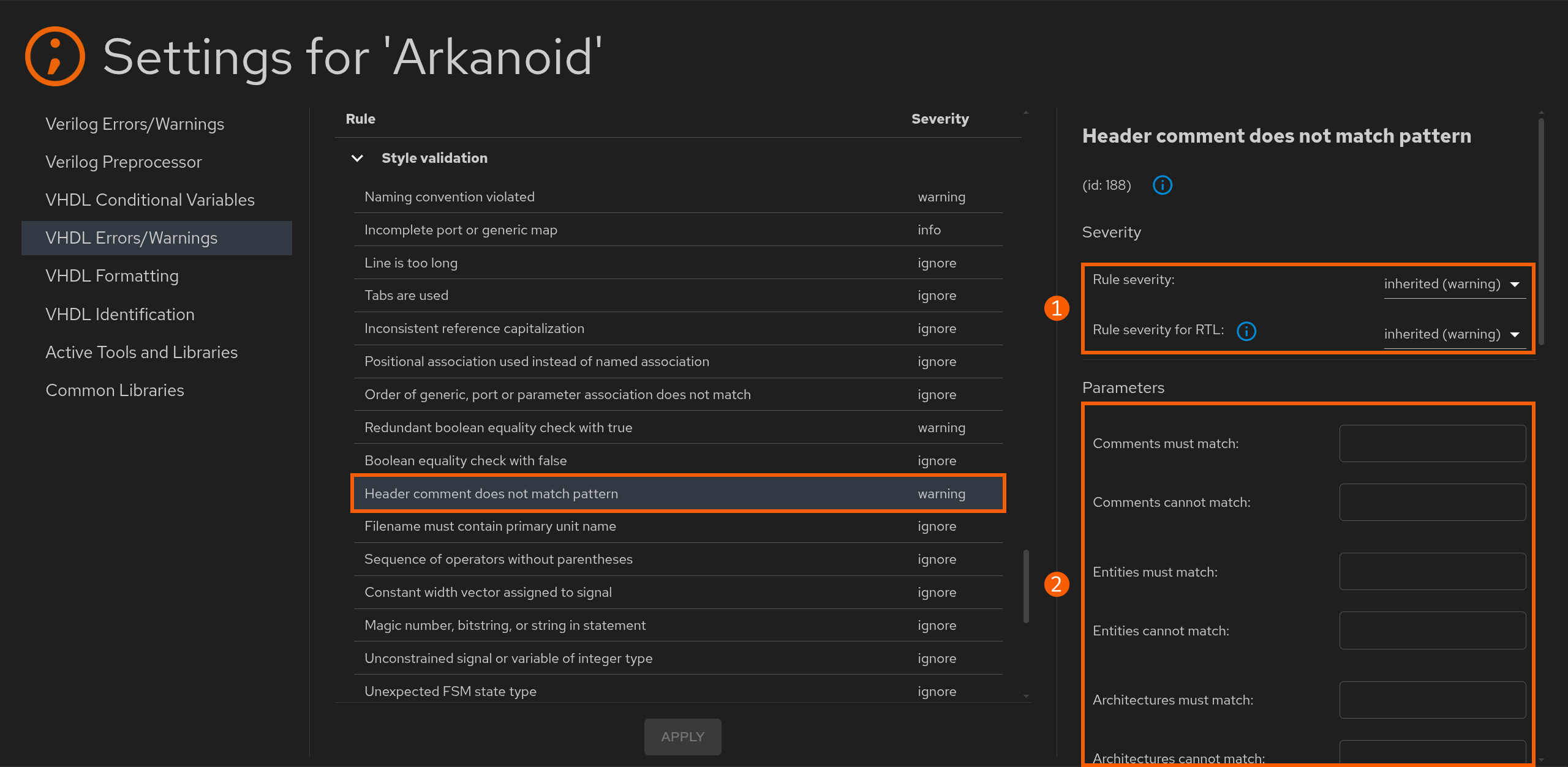
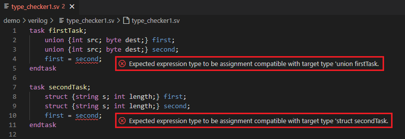
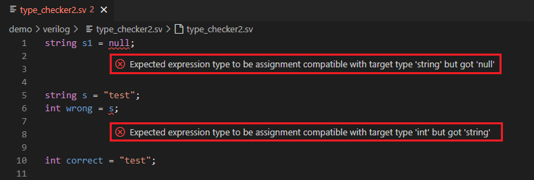
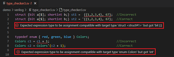
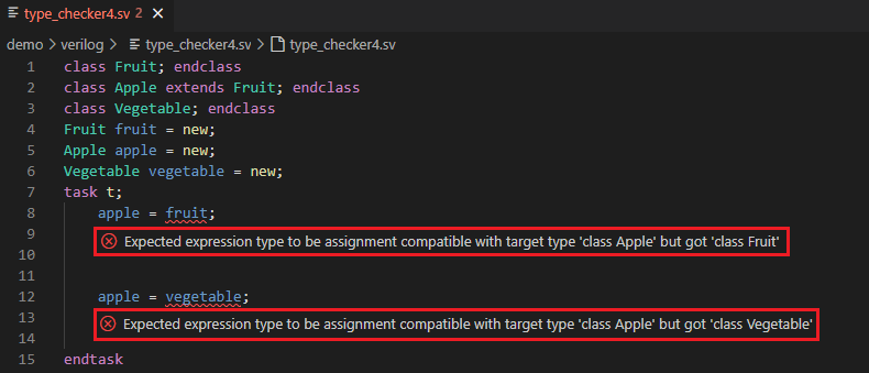
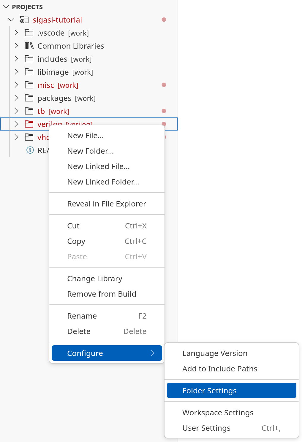
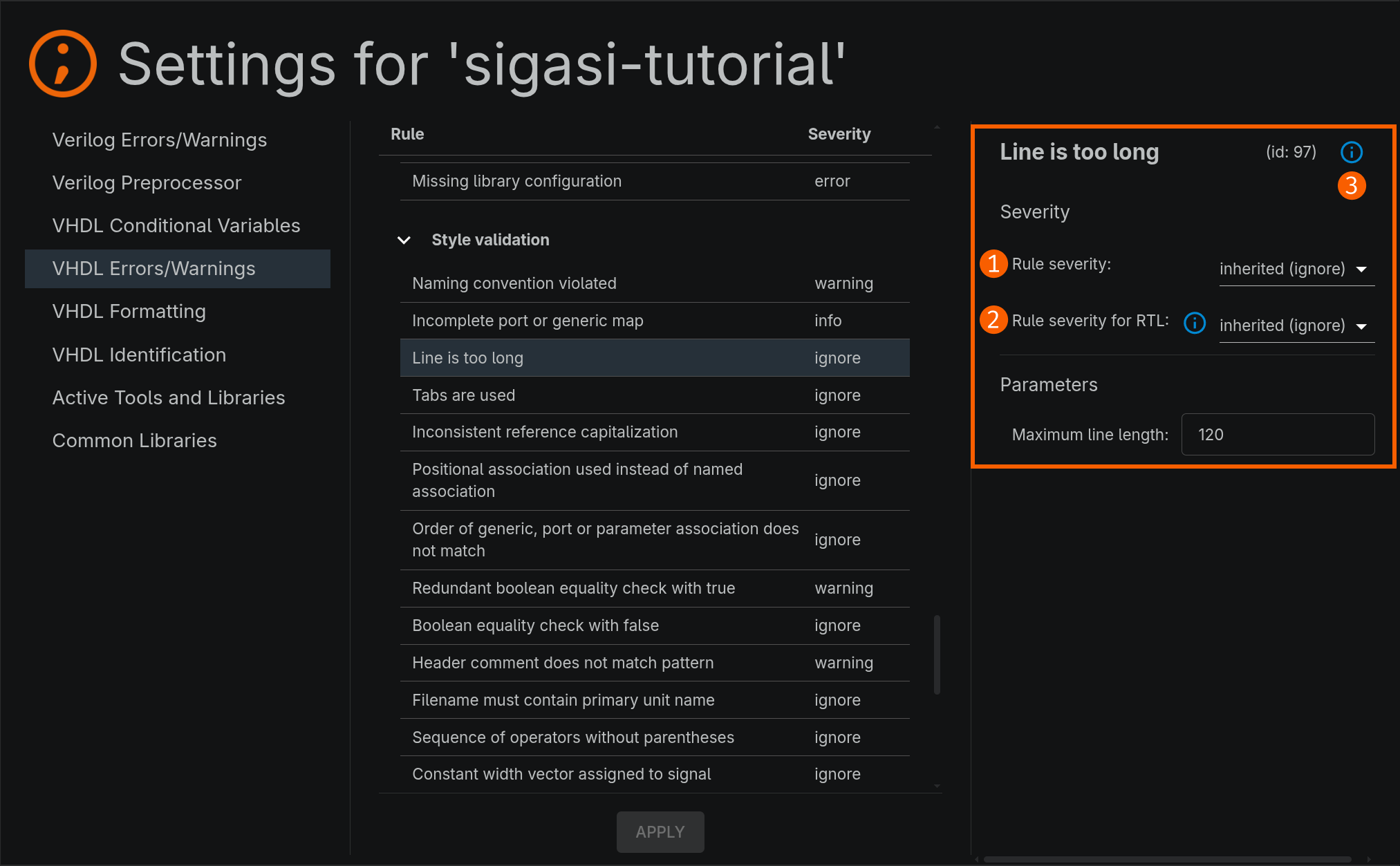
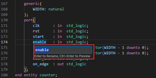
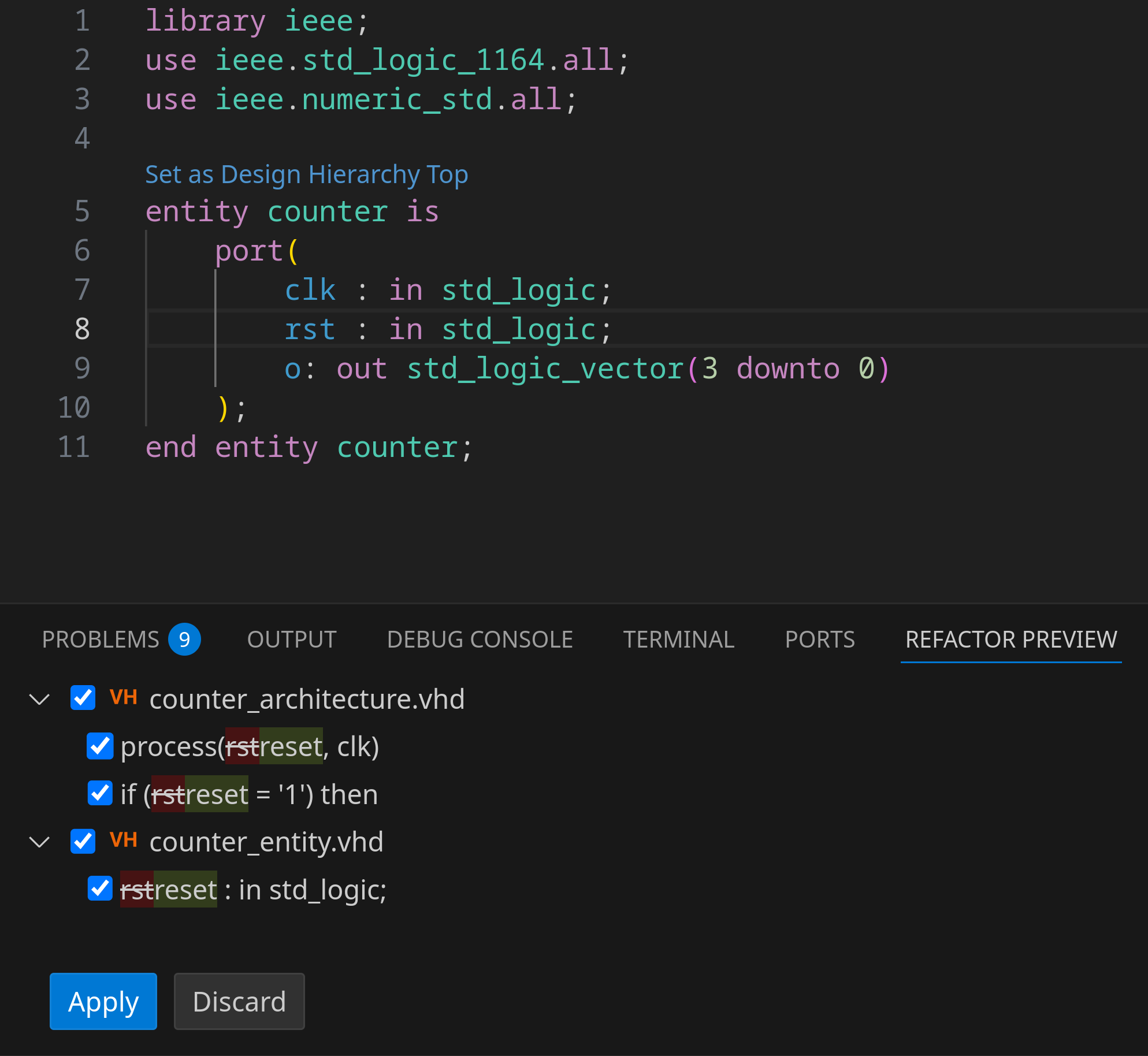
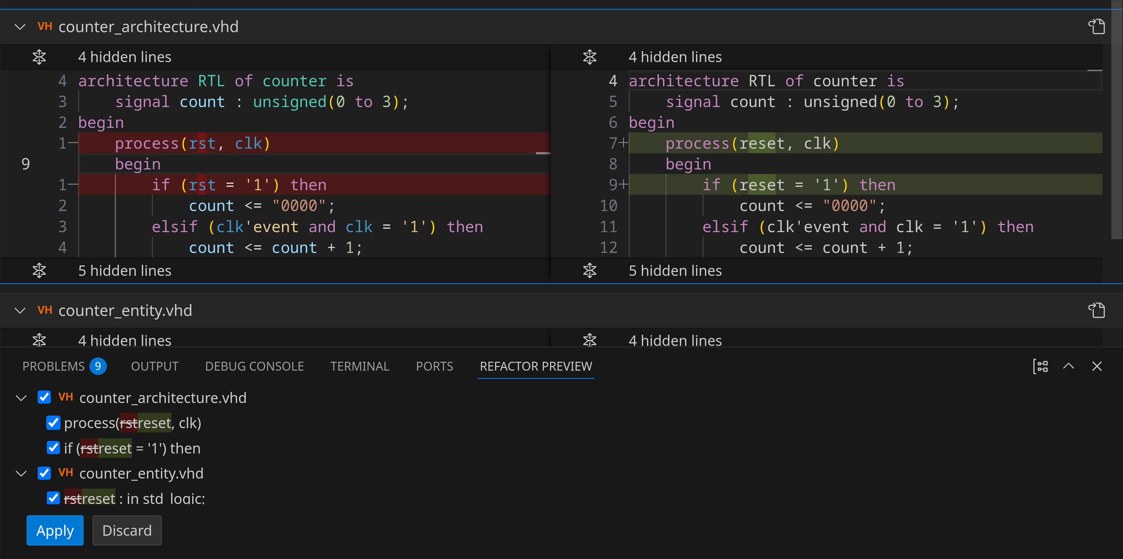
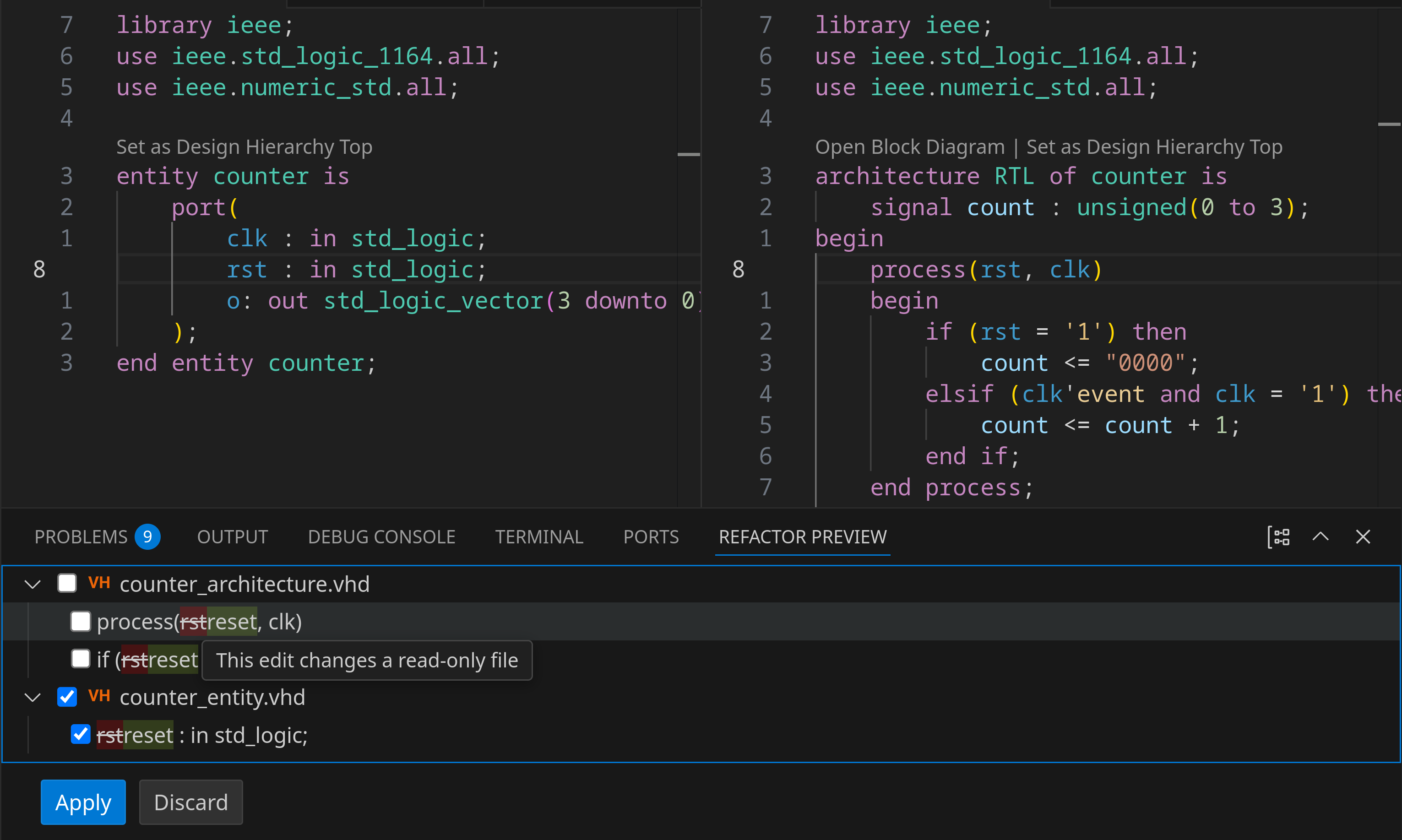
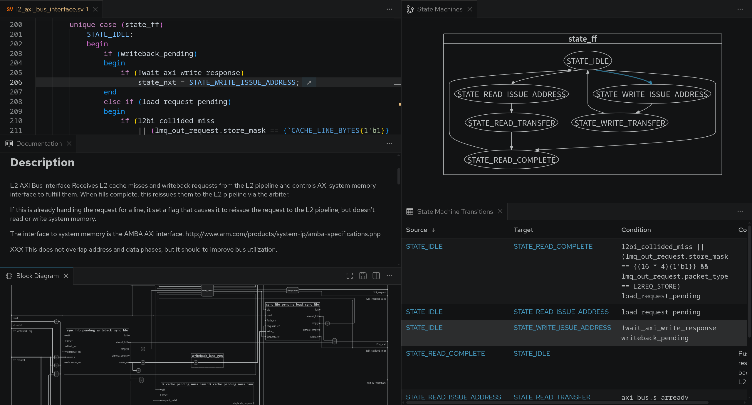

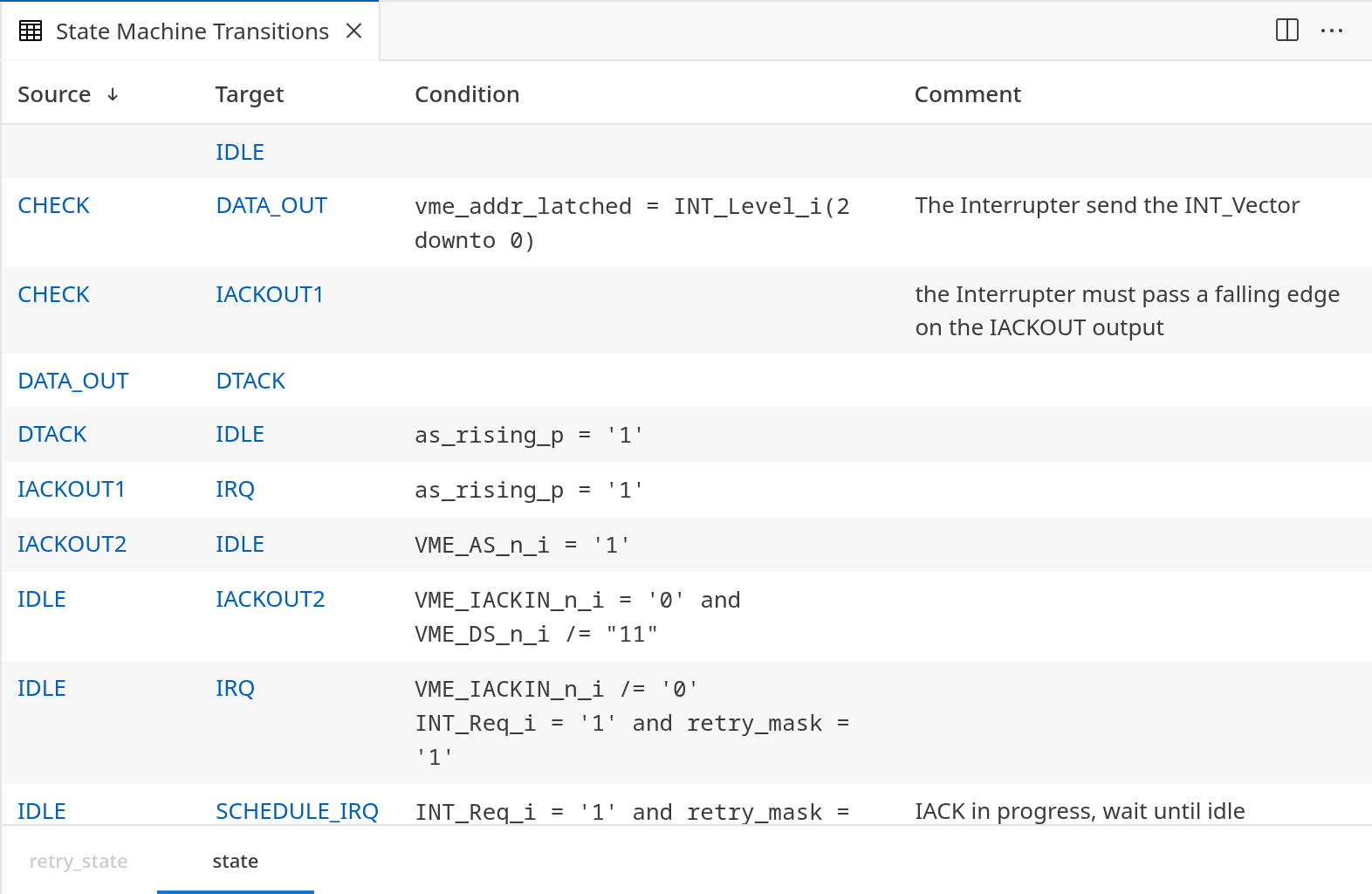
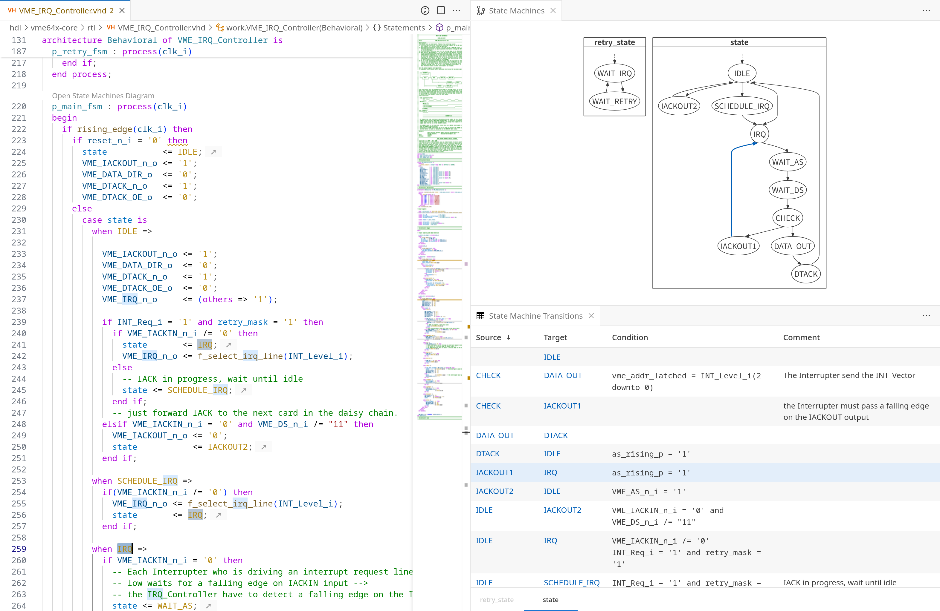
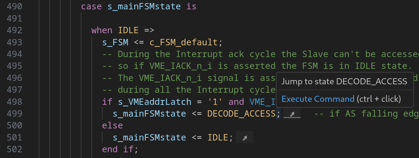
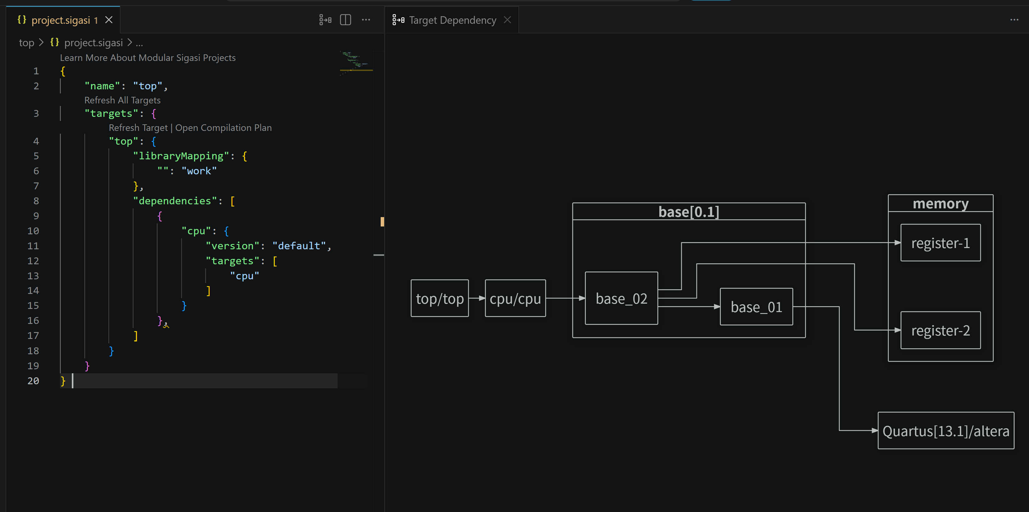
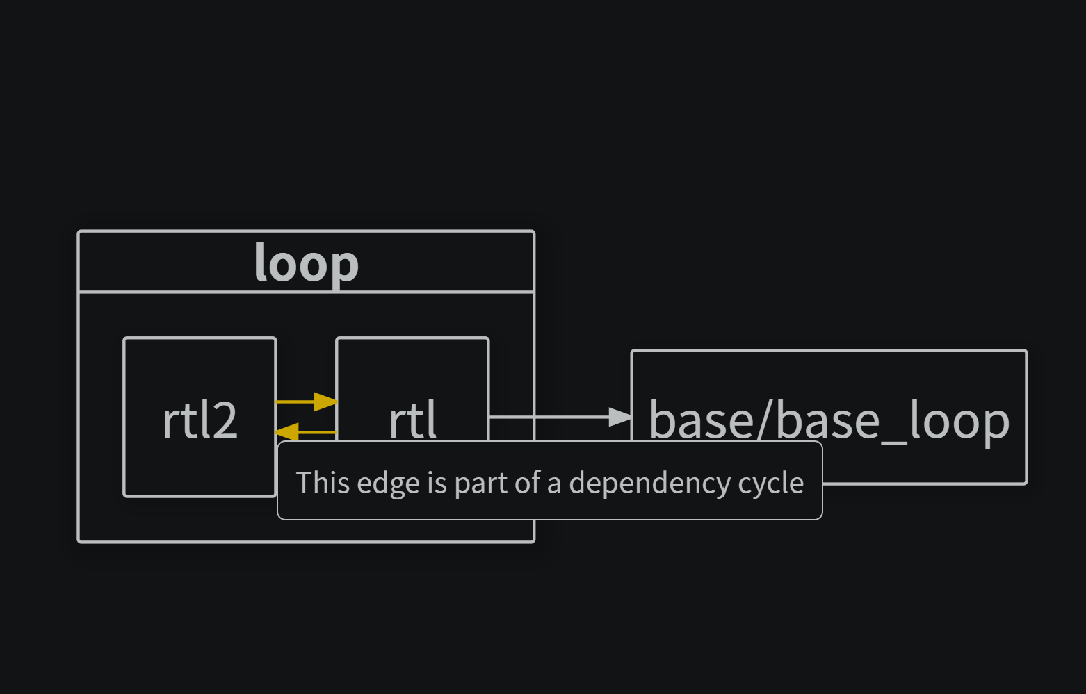
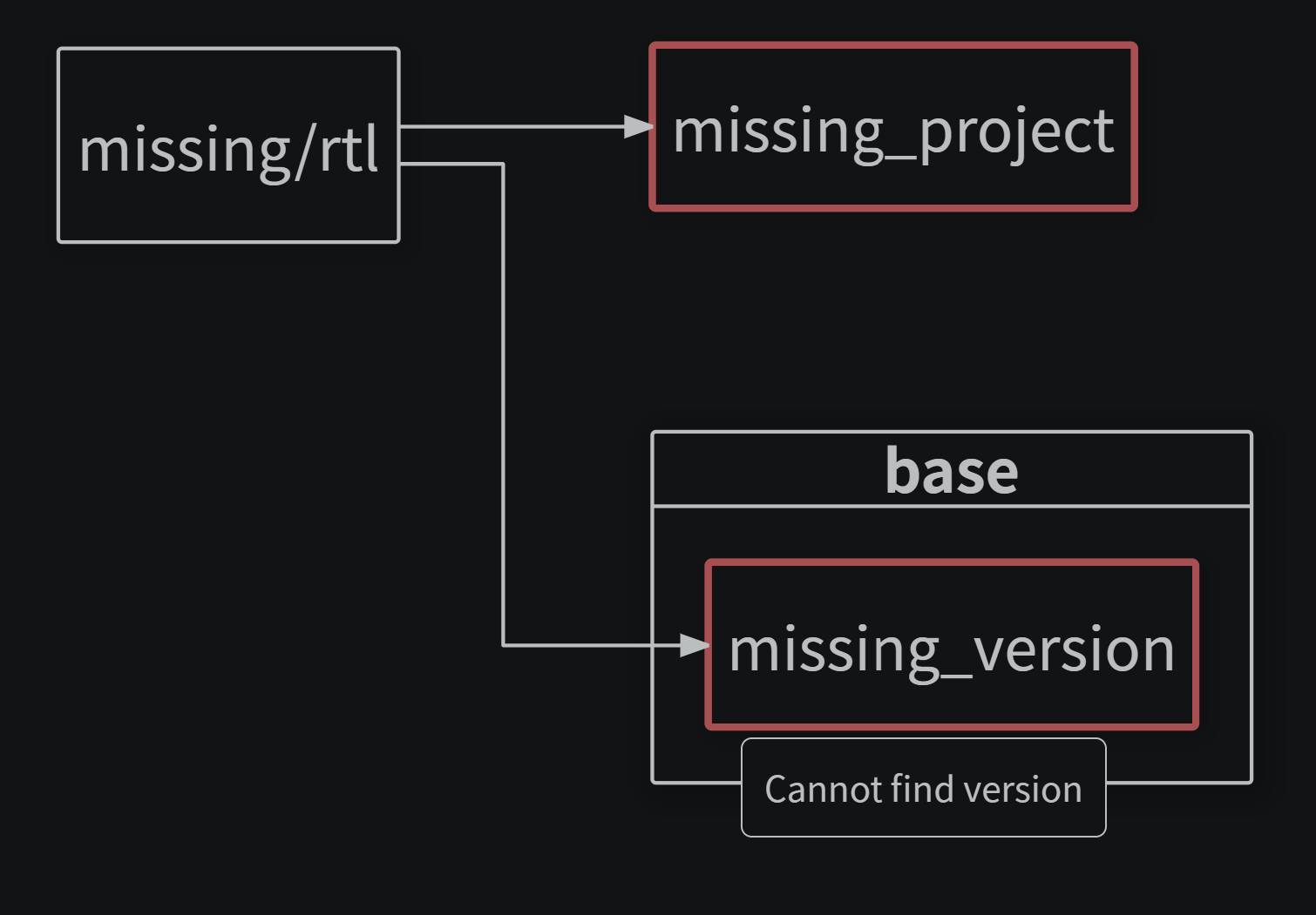
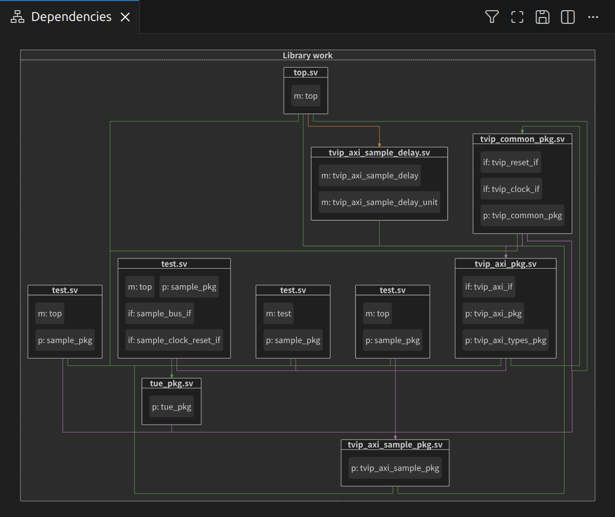
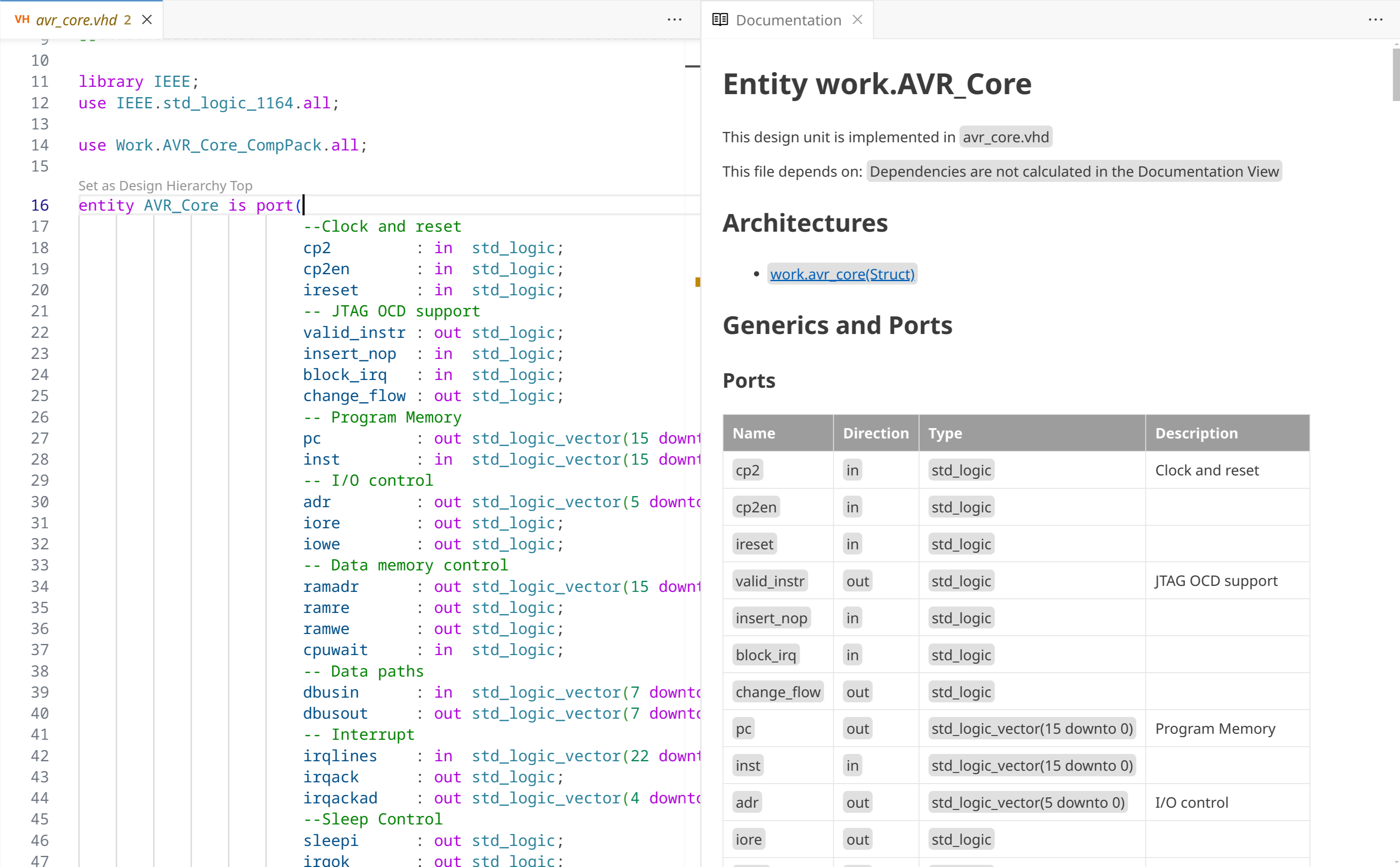
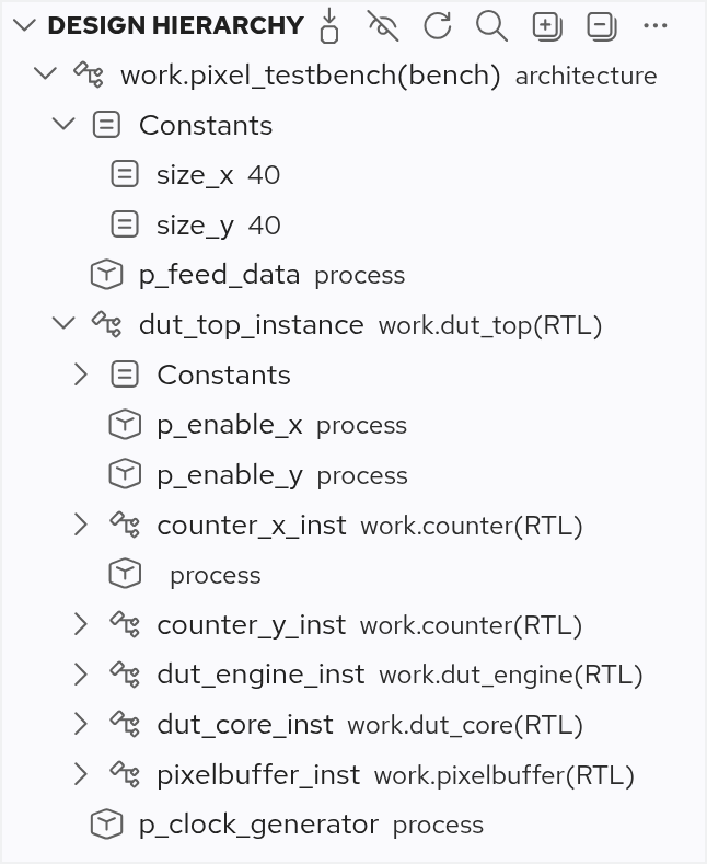
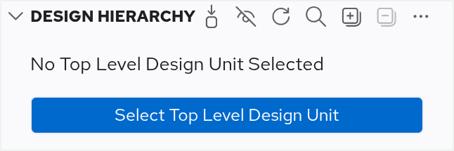
 Select Top Level Design Unit button in the toolbar, a context menu item in the
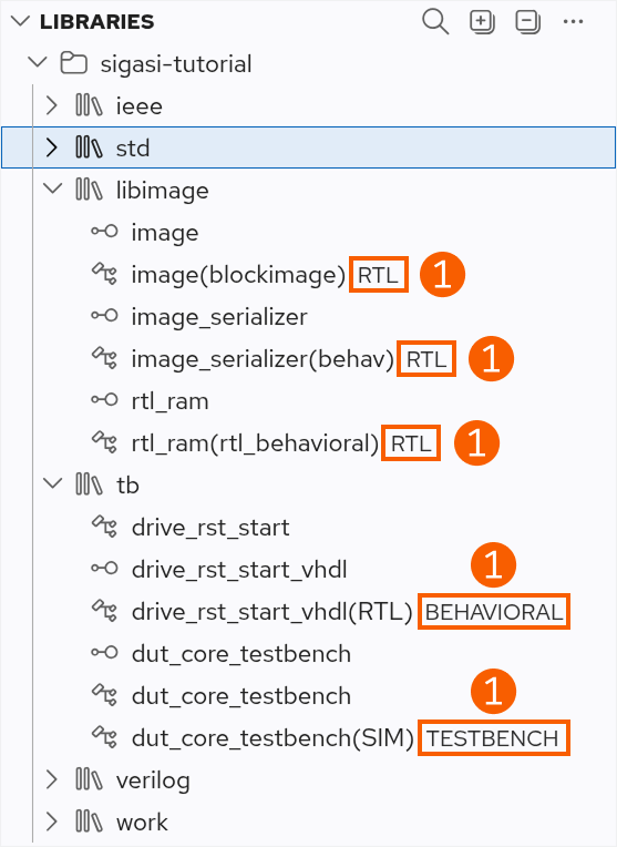
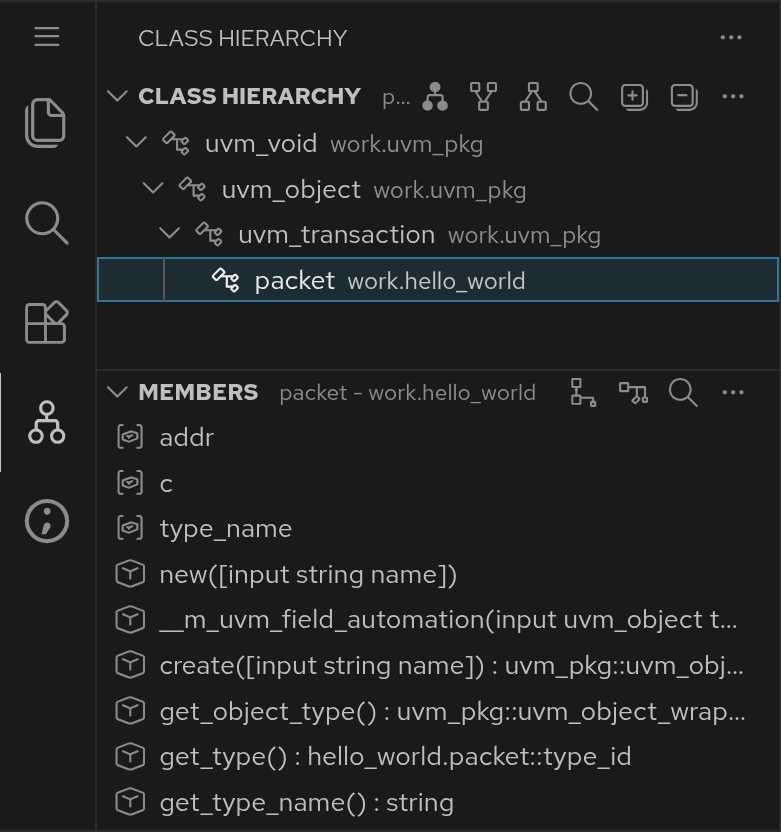
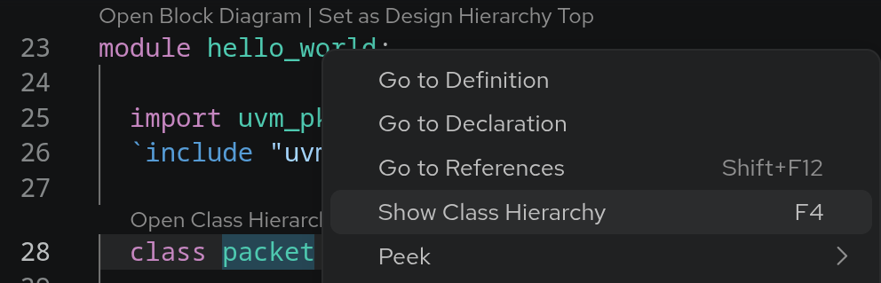


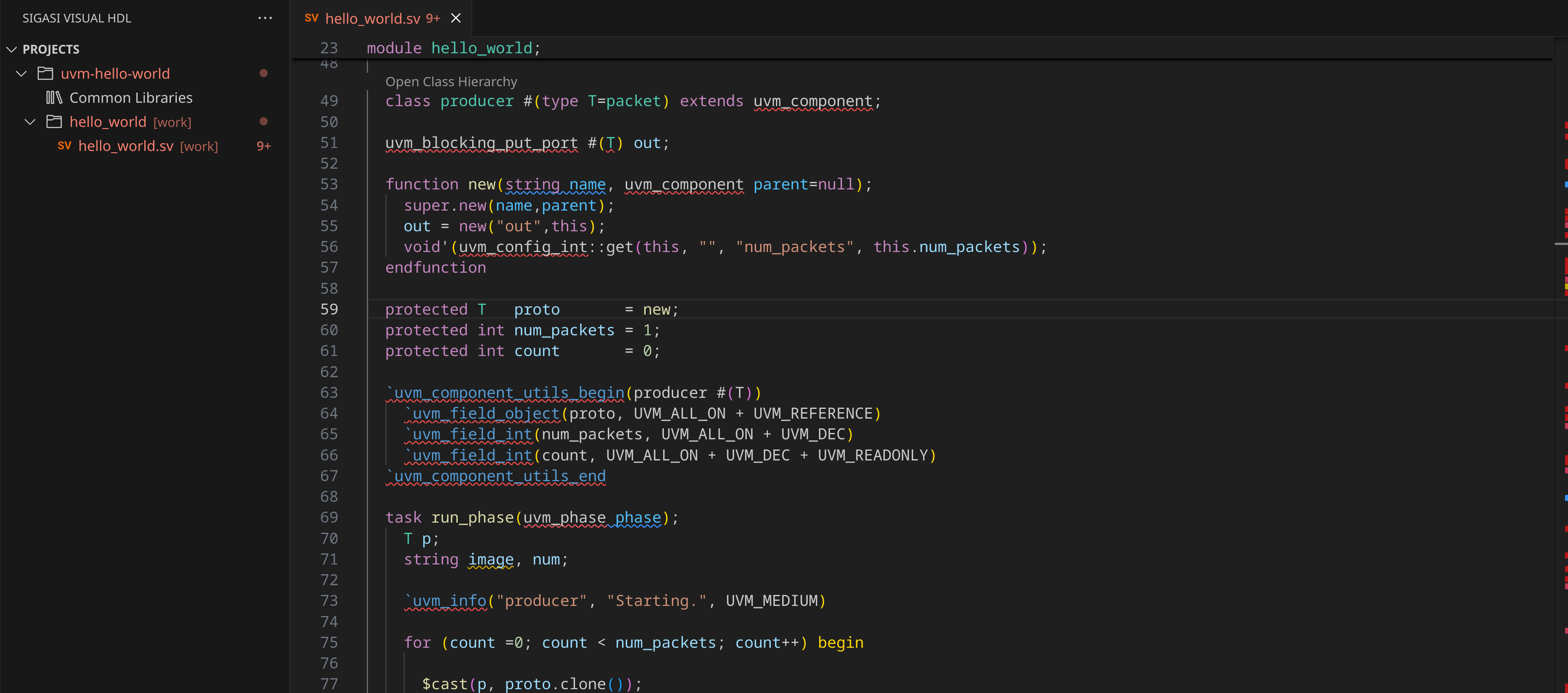
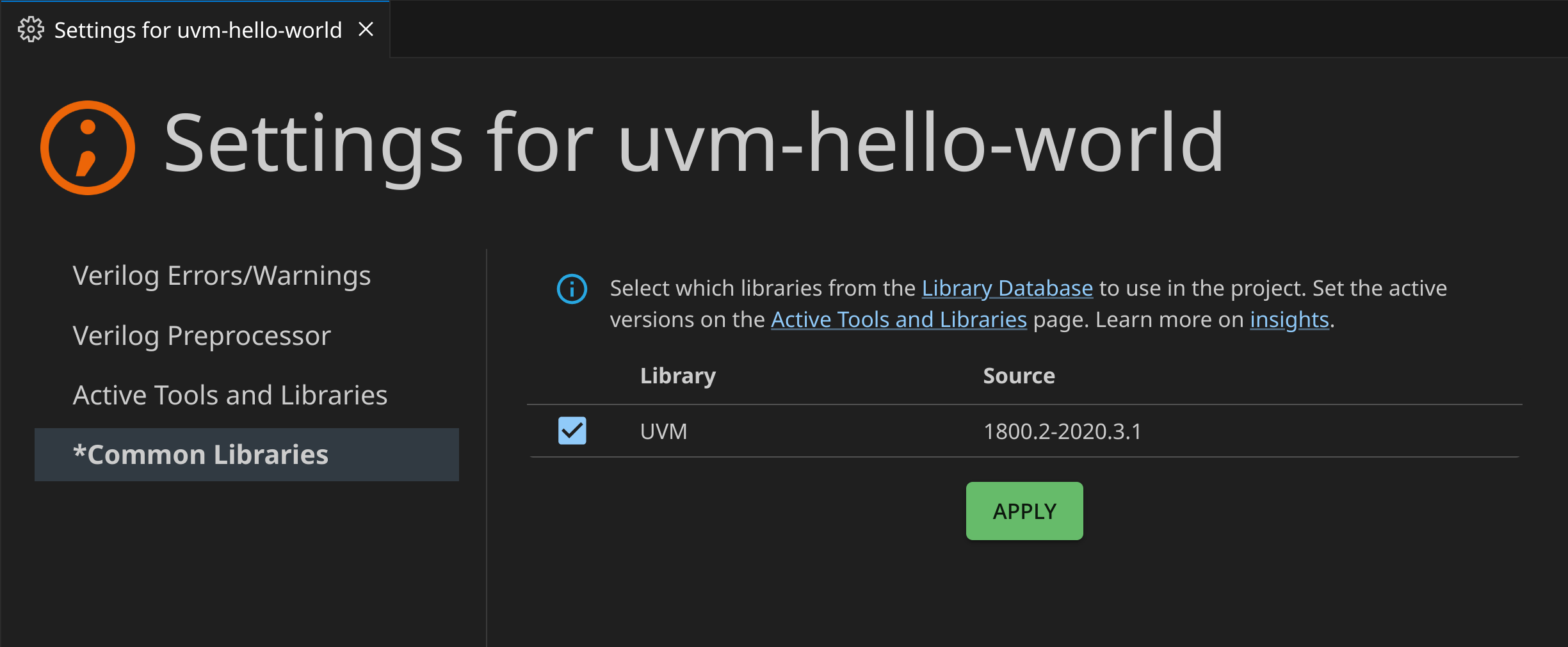
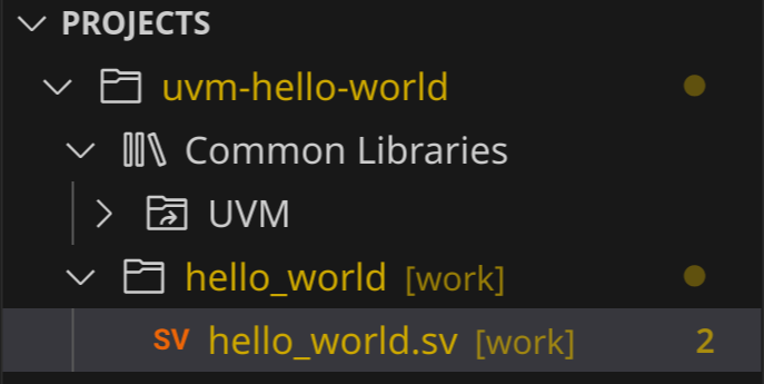
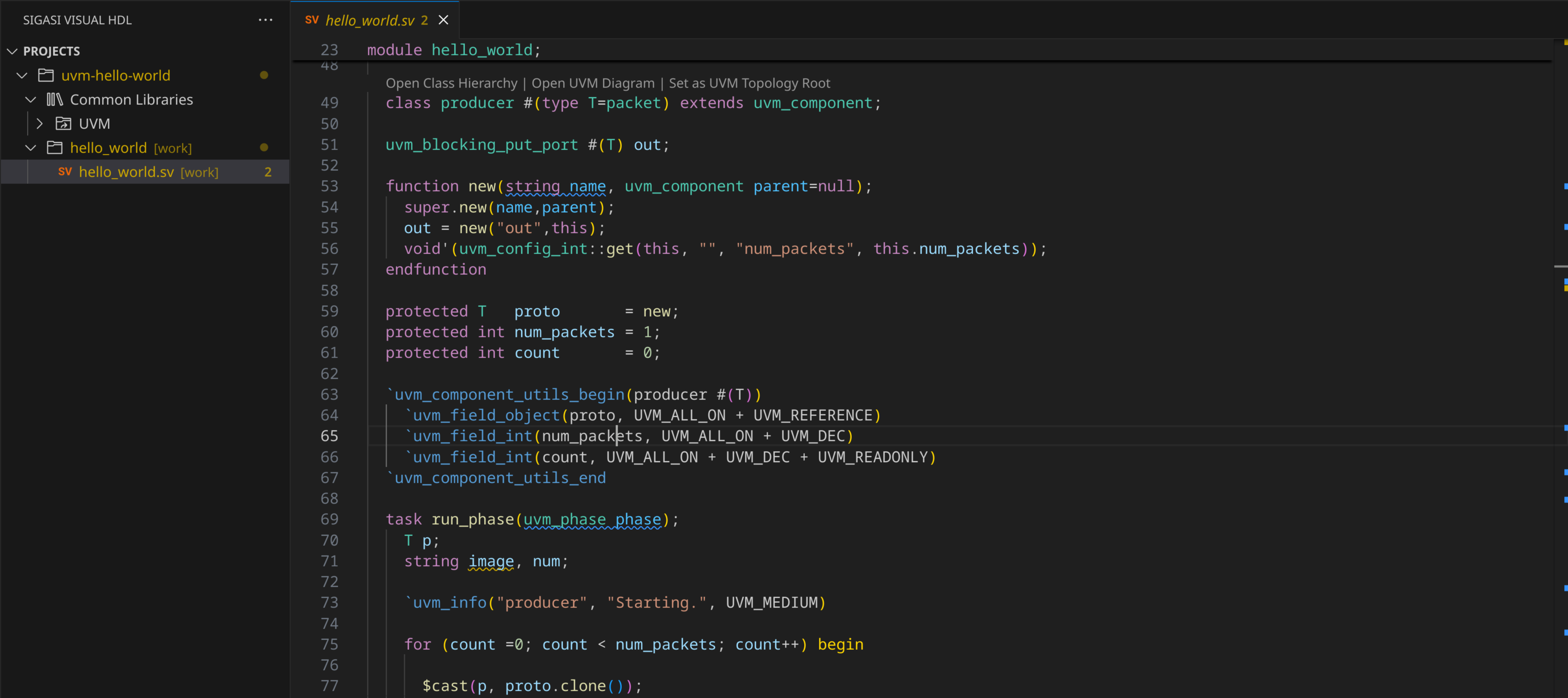
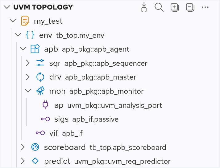
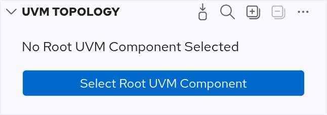
 Select Root UVM Component button in the toolbar, or you can use the
 button in the toolbar.