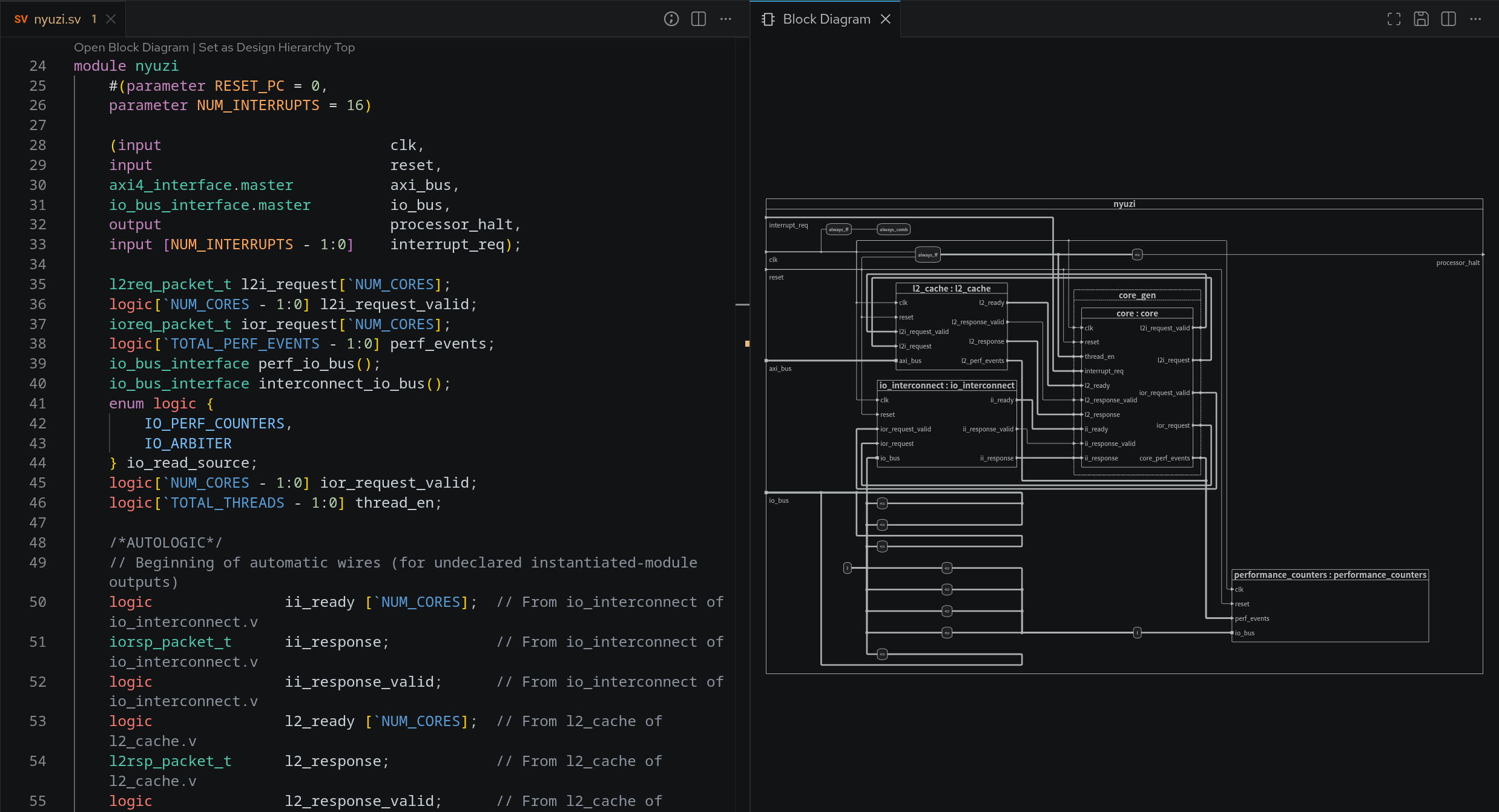
The Block Diagram offers an auto-generated, immutable, graphical view of all modules, architectures, their instantiations, processes, and many more constructs in your selected editor’s Verilog or VHDL code.
This diagram automatically updates while you are editing your code and offers a convenient way to visually inspect and navigate your code, even when it’s unfinished or broken.
You can open the Block Diagram by clicking the Sigasi logo  in the editor toolbar (top right) and selecting Open Block Diagram. Alternatively, you can open the diagram through the Code Lens or via the command palette Ctrl+Shift+P
by typing
in the editor toolbar (top right) and selecting Open Block Diagram. Alternatively, you can open the diagram through the Code Lens or via the command palette Ctrl+Shift+P
by typing Sigasi: Open Block Diagram.
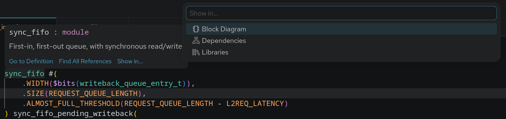
When you click on an element, it’s highlighted. This is especially useful for wires connecting many blocks. By double-clicking blocks, ports, or wires, you navigate to the corresponding HDL code. If you want to go into a block, you right-click it and select Open Module, Open Entity, or Open Architecture. To reveal constructs from your code in the Block Diagram: right-click the construct in the editor, select Show in… in the context menu, and then select Block Diagram in the pop-up menu. Show in… can also be accessed directly from the hover of an applicable code element.
Note that the block diagram is generated automatically from code, but it’s not possible to modify the diagram or generate code from it.
Buttons in the block diagram
- Automatically resizes the block diagram to fit in the current viewport
- Save the diagram as an SVG. Other file formats are not supported
Visualization
You might’ve noticed that there are different kinds of blocks, wires, and ports. The tables below detail which elements are shown in the block diagram and how they’re represented. Additionally, the following rules apply:
- Input & linkage (VHDL only) ports are always on the left
- Output & buffer (VHDL only) ports are always on the right
- In instantiations, ports are placed in the same order as they’re defined in the code
- When right-clicking instantiations, you can open the corresponding module, architecture, or entity in the right-click context menu
- Some blocks can be collapsed or expanded through the right-click context menu
Verilog
| construct | visualization | collapsible |
|---|---|---|
| modules | solid block | ✅ |
| generate block | dotted line block | ✅ |
| always block | rounded block | ❌ |
| instantiation | solid block | ❌ |
| interface instantiation | I in rounded block | ❌ |
| port | solid triangle | ❌ |
| inout port | solid square | ❌ |
| port with interface type | solid square | ❌ |
| assignment | <= in rounded block | ❌ |
| assertion | ⊢ in rounded block | ❌ |
| wire connection | solid line | ❌ |
| port connection | solid line | ❌ |
| multi-bit* connection | thick solid line | ❌ |
| interface connection | thick solid line | ❌ |
| modport connection | thick solid line | ❌ |
* For Verilog, multi-bit is defined as: !bit && !logic
VHDL
| construct | visualization | collapsible |
|---|---|---|
| architecture | solid block | ✅ |
| generate | dotted line block | ✅ |
| block statement | solid block | ✅ |
| process | rounded block | ❌ |
| instantiation | solid block | ❌ |
| port | solid triangle | ❌ |
| inout port | solid square | ❌ |
| open port | hollow square | ❌ |
| assignment | <= in rounded block | ❌ |
| assertion | ⊢ in rounded block | ❌ |
| signal connection | solid line | ❌ |
| port connection | solid line | ❌ |
| vector* connection | thick solid line | ❌ |
* For VHDL, vector is defined as: !boolean && !bit && !std_logic && !std_ulogic