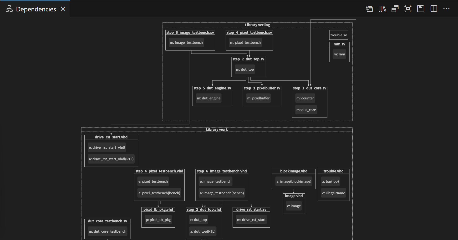
The Dependencies Diagram visualizes the dependencies of your VHDL, SystemVerilog, or mixed-language projects. This view shows the relationships between your source files and makes it easy to see top levels and important packages. The Dependencies Diagram also makes it easy to detect orphaned files.
The view is automatically updated each time you save your files.
You can open the Dependencies Diagram by clicking the Sigasi logo  in the editor toolbar (top right) and selecting Open Dependencies Diagram. Alternatively, you can open the view using the command palette
and typing
in the editor toolbar (top right) and selecting Open Dependencies Diagram. Alternatively, you can open the view using the command palette
and typing Sigasi: Open Dependencies Diagram.
The Dependencies Diagram has the following options:
 shows dependencies of the entire project, which you can uncheck to focus on the active editor dependencies only
 groups design files per library
 shows design units inside design files prefixed with an abbreviation of their kind architecture, module, package, etc.
The Dependencies Diagram can help you navigate, too. Double-click a filename in the diagram to open the corresponding editor.
You can also navigate from your code to the Dependencies Diagram. To reveal a specific design unit: right-click it, select Show In… in the context menu, then select Dependencies Diagram in the pop-up menu. Show In… can also be accessed directly from the hover of an applicable code element.
You can export this diagram for documentation by clicking the save button.