The Dependencies Diagram visualizes the dependencies of your Verilog, VHDL, and mixed-language projects. This diagram shows the relationships between your source files and makes it easy to see top levels (no incoming elaboration dependency edges, only outgoing) and important packages. The Dependencies Diagram also makes it easy to detect orphaned files (no incoming nor outgoing edges).
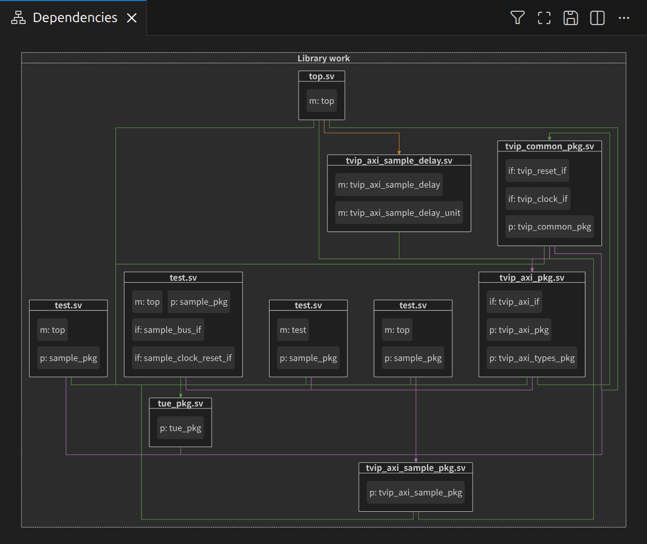
The diagram is automatically updated each time you save your files or change your project setup. A dependency is visualized through arrows between two blocks. For example, A ⭢ B means that A depends on B. The diagram shows three types of dependencies:
| Type | Color | Examples |
|---|---|---|
| Preprocessor | Purple | Macro invocations or checks in ifdef/ifndef directives. Note that included files are not shown in the diagram |
| Compilation | Green | Package imports in Verilog, references to design units in VHDL |
| Elaboration | Orange | Design unit instantiations |
You can open the Dependencies Diagram by clicking the Sigasi logo  in the editor toolbar (top right) and selecting Open Dependencies Diagram. Alternatively, you can open the diagram using the command palette Ctrl+Shift+P
and typing
in the editor toolbar (top right) and selecting Open Dependencies Diagram. Alternatively, you can open the diagram using the command palette Ctrl+Shift+P
and typing Sigasi: Open Dependencies Diagram.
The Dependencies Diagram is often used for visual navigation. In the diagram you can double-click:
- Filenames – to open the corresponding file editor,
- Design units – to navigate to their declaration,
- Dependency edges – to navigate to the first reference that created a dependency (e.g., package import, design unit instantiation, or macro invocation).
You can also navigate from your code to the Dependencies Diagram. To reveal a design unit: right-click it, select Show in… in the context menu, and then select Dependencies in the pop-up menu. Show in… can also be accessed directly from the hover of a design unit. The Design Units need to be visible to use Show in….
Note that no elaboration is performed. Thus, instantiations in conditionally generated blocks will always create elaboration dependencies, even if the condition is not fulfilled in the current configuration.
Buttons in the dependencies diagram
Opens the View Options menu to show or hide elements in the diagram. The icon changes to when any option is filtered. The menu offers the following options:
Option Description Show dependencies of all project files Show the dependencies of the entire project or only those of the file in the active editor Show targets Group design files per project target Show libraries Group design files per library Show design units Show/hide design units inside design files prefixed with an abbreviation of their kind Show preprocessor dependencies Show/hide preprocessor dependency edges Show compilation dependencies Show/hide compilation dependency edges Show elaboration dependencies Show/hide elaboration dependency edges Automatically resizes the block diagram to fit in the current viewport
Save the diagram as an SVG. Other file formats are not supported
Design unit prefix table
Verilog
| Prefix | Design unit kind |
|---|---|
cf | Config |
ch | Checker |
if | Interface |
m | Module |
p | Package |
pr | Program |
u | UDP (User-Defined Primitive) |
VHDL
| Prefix | Design unit kind |
|---|---|
a | Architecture |
b | Package body |
c | Configuration |
e | Entity |
i | Package instantiation |
p | Package |
x | Context |