Sigasi Visual HDL Professional Edition or Sigasi Visual HDL Enterprise Edition
The State Machines Diagram displays a graphical (bubble diagram) view of all state machines in your current VHDL or SystemVerilog editor. This viewer automatically updates while you are editing your code and offers a convenient way to visually inspect and navigate your code, even when your code is unfinished or broken.
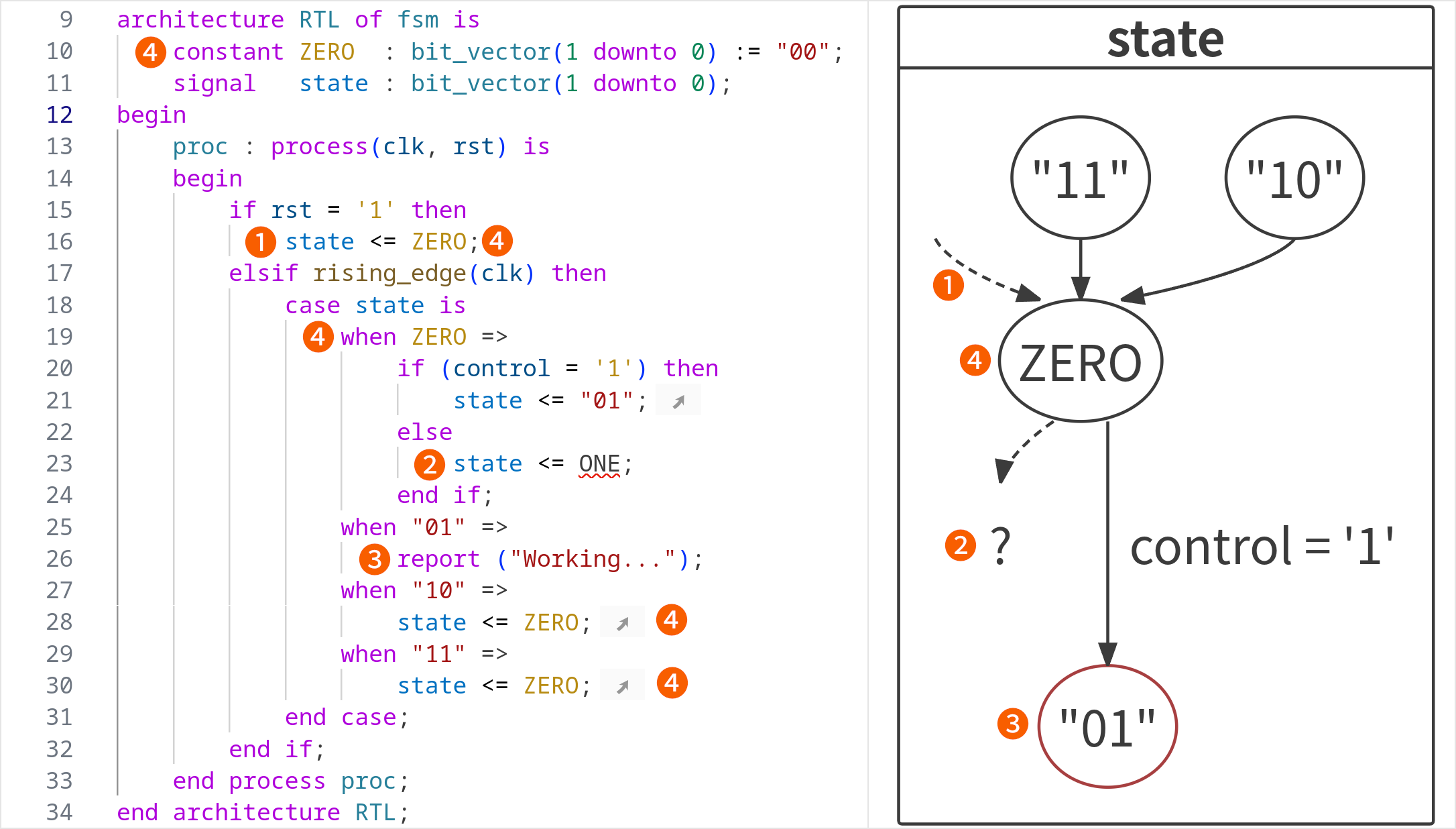
- Reset state (dashed arrow): The state that will be assigned when the state machine is reset
- Unresolved state (dashed arrow to a
?): Sigasi found a state transition but cannot determine the end state - Dead state (red outline): States that do not have any outgoing transitions
- State names: When a constant name is consistently used to refer to a state, its name will also be used in the diagram
- Unused state (red): States that are fully isolated and have no transitions

You can open the State Machines Diagram by clicking the Sigasi logo  in the editor toolbar (top right) and selecting Open State Machines Diagram. Alternatively, you can open the view using the command palette
and typing
in the editor toolbar (top right) and selecting Open State Machines Diagram. Alternatively, you can open the view using the command palette
and typing Sigasi: Open State Machines Diagram.
If you have documented your state transitions (i.e., the assignments), the comments will be added as text to the transitions in the view.
You can double-click nodes or transitions to navigate to the corresponding HDL code.
With the hide comments button, you can toggle the display of comments on edge labels.
With the hide conditions button, you can toggle the display of comments on edge labels. These labels show the code comments of the transition statements.
You also have the option to Zoom In, Zoom Out, or Zoom to Fit.
The State Machines Diagram can be exported to an SVG using the save button.