Introduction
This article starts with elaborating the necessity for rigor FSM design and its key objectives. It provides exemplary implementations of good practices. Finally, it goes over a step by step example of building an FSM with the help of Sigasi Visual HDL (SVH) on VS Code.
The Critical Need for FSM Design Thoroughness
Finite State Machines (FSMs) represent one of the most critical and error-prone aspects of digital hardware design. As highlighted in industry literature, poorly implemented FSMs have caused decades of expensive failures, silicon respins, and field returns in safety-critical applications. When an FSM enters an undefined state in production hardware, consequences range from system lockups to catastrophic failures.
Modern semiconductor companies enforce rigorous FSM coding standards to address five essential objectives:
- Robust Functionality: Predictable behavior under all conditions
- Functional Safety: Prevention of hazardous undefined behaviors
- Synthesis Reliability: Consistent hardware implementation across tools
- Verification Completeness: Enabling thorough validation
- Maintainability: Code that’s understandable and modifiable
Exemplary FSM Implementations
Lukas Vik’s open-source VHDL components demonstrate excellent FSM design principles in practice. Consider these examples from his GitHub repository:
AXI-Lite Register File (axi_lite_register_file.vhd)
type read_state_t is (ar, r);
signal read_state : read_state_t := ar;
...
read_process : process
begin
  if reset = '1' then
    read_state <= ar;  -- Critical: Hardware-enforced initialization
    -- All control signals reset to safe defaults
  elsif rising_edge(clk) then
    case read_state is
      when ar =>
        read_index <= axi_lite_m2s.read.ar.addr(address_range);
        axi_lite_s2m.read.ar.ready <= '1';
        if axi_lite_s2m.read.ar.ready = '1' and axi_lite_m2s.read.ar.valid = '1' then
          read_state <= r;  -- Clear condition-based transition
        end if;

      when r =>
        axi_lite_s2m.read.r.valid <= '1';
        -- rest of the read state code
    end case;
  end if;
end process;
This implementation uses:
- Explicit enumerated types for states (
read_state_t) - Default state initialization via the reset condition assigning
arstate toread_state - Clean separation of state transition logic
AXI Write Crossbar (axi_simple_write_crossbar.vhd)
type state_t is (idle, wait_for_aw_done, wait_for_w_done, wait_for_b_done);
signal state : state_t := idle;
...
case state is
  when idle => ... -- Arbitration logic
  when wait_for_aw_done => ...
end case;
Key features include:
- Meaningful state names describing functional behavior
- Default assignments preventing unintended latches
- Explicit coverage of all transition cases
- Safe initialization to known idle state
FSM Design Guidelines with VHDL Implementation
Let’s implement a pulse generator FSM that adheres to industry standards. This module generates a single-cycle pulse after a configurable delay when triggered.
Design Requirements
Inputs:
clk: System clockrst_n: Asynchronous active-low resettrigger: Start pulse generationdelay: Configurable delay (clock cycles)
Outputs:
pulse_out: Single-cycle pulse after delay
States:
IDLE: Waiting for triggerCOUNTING: Counting delay cyclesPULSE: Output active
Given the above-mentioned inputs and outputs, we can first start by defining a VHDL entity as follows.
entity pulse_generator is
  generic(
    MAX_DELAY : positive := 16  -- Maximum configurable delay
  );
  port(
    clk      : in  std_logic;
    rst_n    : in  std_logic;
    trigger  : in  std_logic;
    delay    : in  natural range 1 to MAX_DELAY;
    pulse_out: out std_logic
  );
end entity;
Now the second step is to define states of enumerated type and select the way we wish them to be encoded. More details on FSM state encodings is linked in the resources.
architecture rtl of pulse_generator is
  -- State type definition with explicit encoding
  type state_type is (IDLE, COUNTING, PULSE);
  attribute enum_encoding : string;
  attribute enum_encoding of state_type : type is "sequential";  -- Binary encoding

  signal state_reg, state_next : state_type;
  signal counter, counter_next     : natural range 0 to MAX_DELAY;
begin
-- Architecture definition follows
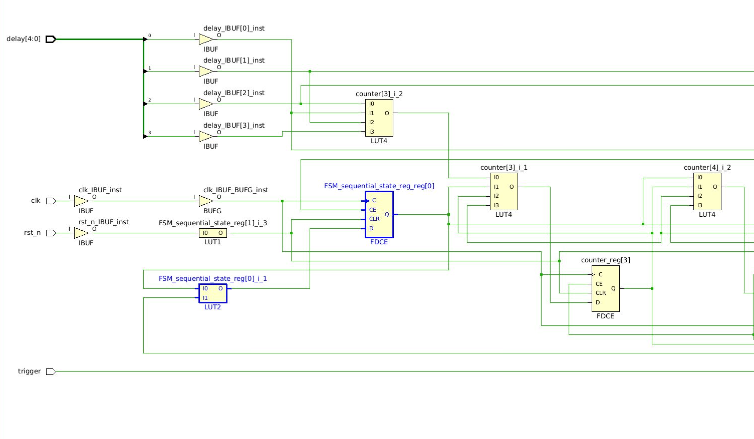
Note: Even though we have specified the encoding, some synthesis tools would still optimize the state machine to a different encoding. Taking a flash forward, by default, Vivado 2021.2 went for one-hot encoding when synthesizing the design. After reviewing synthesis tool settings and explicitly specifying the encoding mechanism for FSM extraction we can see the FSM is encoded as coded as shown below
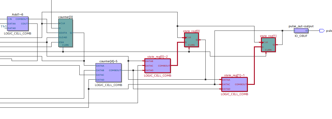
On the other hand, Quartus 2020.1 respected the encoding directly
The key takeaway is, checking the synthesis strategy for FSM extraction is an important step in your workflow to help meet the design requirements effectively.
As we saw in the FSM example of the AXI-Lite register, we need to have a default state for our FSM. To achieve this we define a process holding sequential logic with a reset signal.
  -- State register: Sequential logic with asynchronous reset
  state_register : process(clk, rst_n)
  begin
    if rst_n = '0' then
      state_reg   <= IDLE; -- Reset the state register
      counter     <= 0;    -- Reset other registers in the design
    elsif rising_edge(clk) then
      state_reg   <= state_next;
      counter     <= counter_next;
    end if;
  end process;
If we peek at how the current block diagram of the design looks like so far, we see the following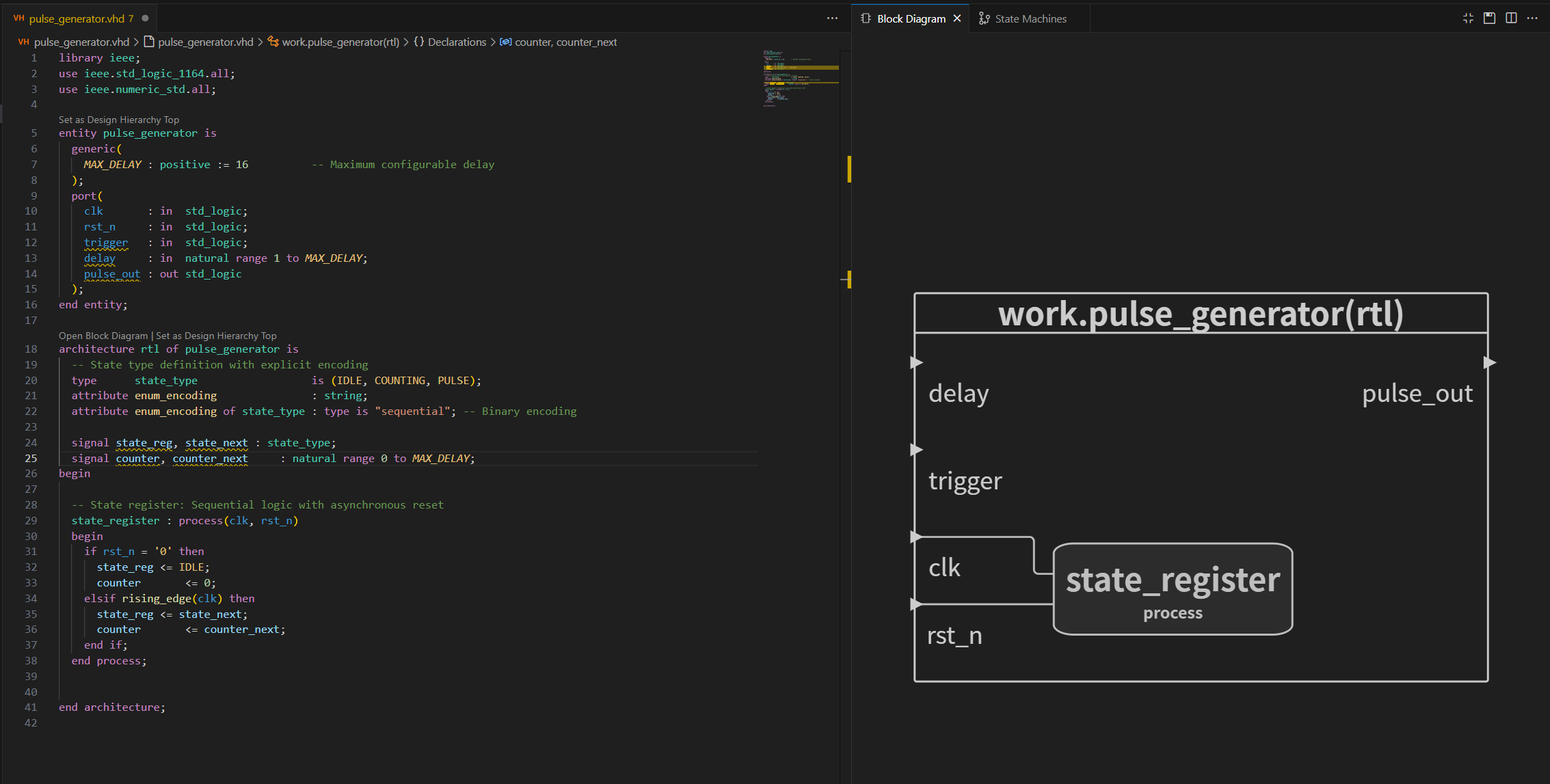
The state_register sequential process has been defined. Since the main logic driving the output is to be defined in the combinational process, the ports are still not connected, and we can see warnings in the code that these signals haven’t been used yet.
Let’s define the combinational logic process that holds the next state logic of the FSM. Initially, we define a default assignment to prevent synthesis tools from inferring latches.
  --Next-state logic: Combinational process
  state_next_logic : process(all)
  begin
    -- Default assignments: Prevent latches
    state_next   <= state_reg;
    counter_next <= counter;
    pulse_out    <= '0';
---

Using VHDL case statement for expressing the FSM next state combinational logic is a conincal way of defining the behavior of the FSM. We can start by typing the overall skeleton and defining what happens in the `IDLE` state as follows.

```vhdl
  case state_reg is
    when IDLE =>
      if trigger = '1' then
        state_next   <= COUNTING;
        counter_next <= delay - 1;    -- Initialize counter
      end if;

    when COUNTING =>

    when PULSE =>

    when others =>                    -- Safe state recovery

  end case;
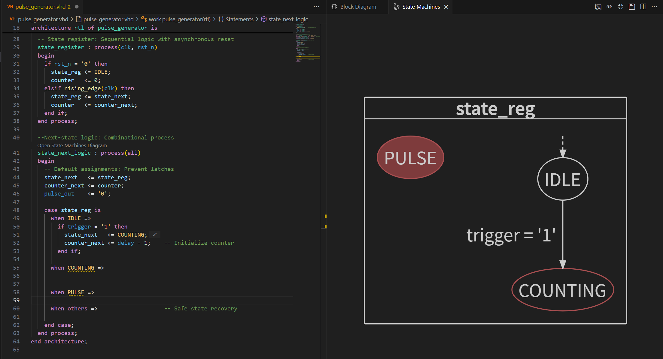
This says, we remain in the IDLE state by default until a trigger signal is received. Also, the counter is set to an initial value that is equal to delay - 1. Now if we peek at the FSM diagram of the current case statement, we see that IDLE case seems to be clear of any issues, and it is the default state since it has the white dashed arrow pointing towards it. However, we see COUNTING and PULSE are still having issues.
Finally, we add the logic of the COUNTING state and the PULSE state. COUNTING has a transition condition that is dependent on the counter value reaching 0; PULSE is a single-cycle state where the pulse_out signal is asserted, and then it defaults back to 0 as specified in the default assignments block of the code. Now the case statement becomes the following
  case state_reg is
    when IDLE =>
      if trigger = '1' then
        state_next   <= COUNTING;
        counter_next <= delay - 1;    -- Initialize counter
      end if;

    when COUNTING =>
      if counter = 0 then
        state_next <= PULSE;
      else
        counter_next <= counter - 1;
      end if;

    when PULSE =>
      pulse_out  <= '1';              -- Generate pulse
      state_next <= IDLE;         -- Send a pulse and get back to idle

    when others =>
      state_next   <= IDLE;
      counter_next <= 0;
  end case;
Taking a look at the final shape of our state machine ..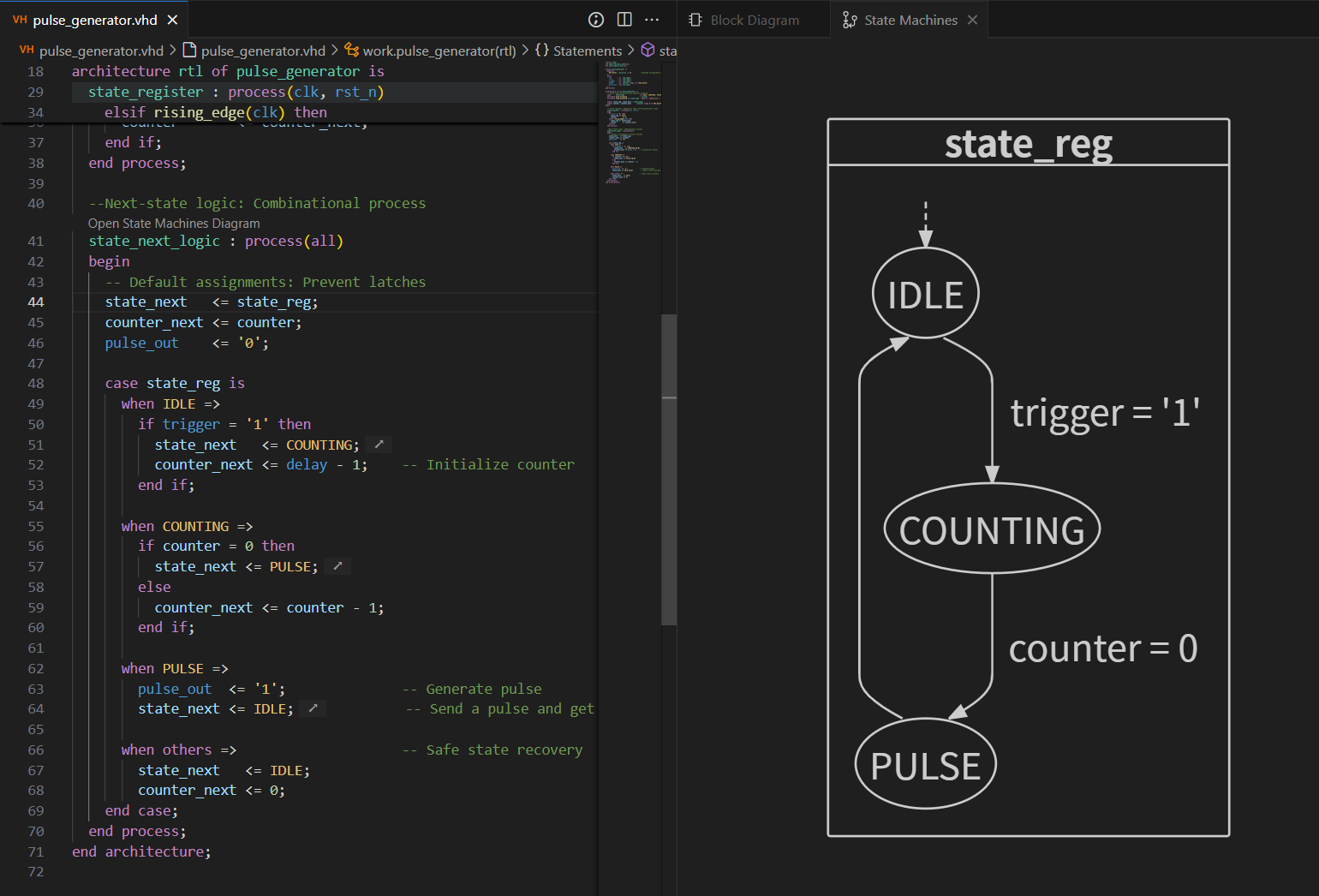
Key Compliance Features Explained
Two-Process Architecture
- Clear separation between sequential state registers and combinational logic
- Follows industry-standard pattern for optimal synthesis
Enumerated State Types
type state_type is (IDLE, COUNTING, PULSE);
- Self-documenting state definitions
- Explicit encoding specification via synthesis attributes
Default Branch for State Recovery
when others =>
  state_next   <= IDLE;
  counter_next <= 0;
- Recovers from illegal states even with “complete” case coverage
- Prevents lockup in unforeseen scenarios
Latch Prevention
-- Default assignments at start of process
state_next   <= state_reg;
counter_next <= counter;
pulse_out    <= '0';
- Guarantees all signals are assigned in all paths
- Eliminates unintended latch inference
Output Implementation
- Moore-type output (
pulse_out) depends solely on current state - Glitch-free implementation within combinational process
Resources
- FSM encoding in VHDL, Wim Meeus, March 6, 2020
- Designing FSMs in VHDL , Asmund Braathen, December 18, 2023
- HDL-Modules , Lukas Vik