In digital design, resets are used to bring a circuit into a predefined state after power-up. This article focuses on how to design resets for synchronous digital circuits in Verilog and SystemVerilog.
Resets are designed in synchronous (clocked) parts of the design. A reset is either asynchronous or synchronous. An asynchronous reset activates as soon as the reset signal is asserted. A synchronous reset activates on the active clock edge when the reset signal is asserted. The choice between a synchronous or asynchronous reset depends on the nature of the logic being reset and the project requirements.
Advantages and disadvantages of synchronous resets include:
- The timing of a synchronous reset is predictable: at the clock edge
- A synchronous reset is robust among others against glitches
- In ASIC technology, smaller flip-flops may be used…
- … but the reset is implemented in additional logic, which may add latency
- Timing closure of a large reset net may be challenging
Advantages and disadvantages of asynchronous resets include:
- Reset can happen regardless of whether the clock is running, e.g. in early stages of circuit start-up or when using clock gating
- Lower latency is achievable because the reset circuitry is not part of the data path
- Glitches on the reset net can lead to spurious resets
- One must ensure that the de-assertion of the reset doesn’t happen at or near a clock edge
In general, synchronous resets are recommended unless the particular circuit requires an asynchronous reset. The choice may depend on the technology used, e.g. some FPGA blocks may only support a synchronous reset. One place where asynchronous resets may be required is for inout and output pins of a chip, so these can be brought to a safe state before a clock is running. A more in-depth discussion of synchronous vs. asynchronous resets is presented in this , this , and this article.
Asynchronous and synchronous reset
The following piece of code shows a standard implementation of a synchronous process with an asynchronous reset. As soon as the reset signal rst is driven high, a reset is executed. If reset is low, the normal operation activates on every rising clock edge.
always_ff @(posedge clk, posedge rst) begin
    if (rst) begin // Test for reset high
        // Reset action
        my_logic <= 0;
    end
    else begin
        // Normal operation
        my_logic <= data;
    end
end
Note the use of always_ff for synchronous processes. The always_ff procedure was introduced in SystemVerilog, restricting the procedure body to only synchronous, or clocked, logic. If you are using plain Verilog, you’ll need to replace always_ff with always.
The code snippet below shows a standard implementation of a synchronous process with a synchronous reset. The process is activated only on a rising clock edge, at which time either a reset or the normal operation is executed.
always_ff @(posedge clk) begin
if (rst) begin
// Reset action
my_logic <= 0;
end
else begin
// Normal operation
my_logic <= data;
end
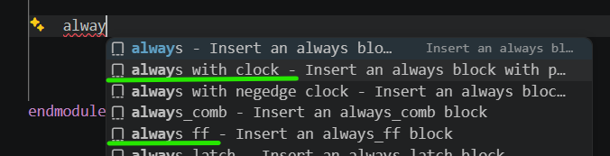
endThese ways of coding resets in Verilog and SystemVerilog are straightforward and efficient for simulation. Sigasi Visual HDL can generate code templates for clocked always and always_ff processes. Simply type the first characters of always and select always with clock - Insert an always block… or always_ff - Insert an always_ff block as needed. Further information on the Content Assist and Autocomplete can be found in the manual.
An alternative way of coding a synchronous reset is shown below. At the clock edge, the normal operation executes. If reset is active, the result of the normal operation is overridden by the reset action.
always_ff @(posedge clk) begin // Synchronous reset
    // Normal operation
    my_logic <= data;
    if (rst)
    begin
        // Reset action
        my_logic <= 0;
    end
end
This coding style may be less intuitive and slightly slower in simulation, but it is equally valid and RTL synthesis will return the same result. Note that also an asynchronous reset can be coded as an override at the end of the process.
Resets: it’s all or nothing
One thing to remember is that one should either reset all signals written by a process, or none. This rule is useful for clarity in the first place. Not resetting a subset of signals written in a process may result in unintended circuit behavior or RTL synthesis may add unwanted circuitry such as latches, clock enables or more logic gates.
// Synchronous reset -- BAD EXAMPLE!!
always_ff @(posedge clk) begin
    if (rst) begin
        // Reset action: reset of q2 is missing
        q1 <= 0;
    end
    else begin
        // Normal operation
        q1 <= data1;
        q2 <= data2;
    end
end
In this case, only q1 is reset, while q2 is left untouched during a reset operation. The behavior may be correct, because the value of q2 may not be important after reset. RTL synthesis, however, will introduce circuitry to ensure that q2 maintains the same state during reset, adding logic and maybe also delay to the circuit.
// Asynchronous reset -- BAD EXAMPLE!!
always_ff @(posedge clk, posedge rst) begin
    if (rst) begin
        // Reset action: reset of q2 is missing
        q1 <= 0;
    end
    else begin
        // Normal operation
        q1 <= data1;
        q2 <= data2;
    end
end
The same applies when the reset is asynchronous. The logic to have q2 keep its state during reset gets an asynchronous input, which will have a negative impact on RTL synthesis and circuit timing.
// Synchronous reset -- BAD EXAMPLE!!
always_ff @(posedge clk) begin
    // Normal operation
    q1 <= data1;
    q2 <= data2;
    if (rst) begin
        // Reset action: reset of q2 is missing
        q1 <= 0;
    end
end
Using the alternative coding style, not resetting all signals leads to different behavior. In this case, q1 will be reset while q2 will continue operating normally during reset. If that is the intended behavior, it would be better for clarity to assign q1 and q2 in separate processes.
So the best practice is: if a synchronous process has a reset, make sure to reset all signals written in the process.
Reset polarity
The above examples all contain a test if (rst) to check whether a reset has to be performed. This is called an active-high reset. The alternative, an active-low reset, would reset the circuit when the reset signal is low. Both active-high and active-low resets are valid.
The choice between active-high and active-low depends on the application and the implementation platform. For example, if your project targets an ASIC technology featuring flip-flops with an active-low reset input, active-low reset may be the best choice. Or, for an FPGA project, it depends on the specific FPGA technology whether active-high (or -low) resets can be implemented more efficiently than the other type. Especially on high-fanout nets, choosing the wrong reset type can lead to timing violations.
For clarity, it is good practice to add a _n (not/negative) or _b (bar) suffix to active-low reset signal names. An example of an active-low, asynchronous reset is shown below. Note that the sensitivity list now contains the falling edge of reset, and that the if-test checks for the inverse of the reset signal.
// Asynchronous, active-low reset
always_ff @(posedge clk or negedge rst_n) begin
    if (!rst_n) begin // Reset asserted (low)
        // Reset action
        my_logic <= 0;
    end
    else begin
        // Normal operation
        my_logic <= data;
    end
end
For reusability, e.g. for IP blocks, you may want a configurable reset polarity. This can be achieved with a constant, a parameter or a preprocessor constant, as in the example below:
always_ff @(posedge clk) begin
   // Synchronous reset
    if (rst == reset_active_value) begin
        // Reset action
        my_logic <= 0;
    end
    else begin
        // Normal operation
        my_logic <= data;
    end
end
In the above example, the reset polarity is determined by reset_active_value. reset_active_value could be either a (local) constant, a module parameter or a preprocessor constant. All three have advantages and drawbacks.
- A (local) constant ensures consistency inside the module, but not across different modules or files, so this approach is not recommended.
- A module parameter needs to be propagated throughout the project. Complex projects with a mix of reset polarities would require this approach. Mixing reset polarities is not recommended, but IP cores from external suppliers may come with different reset polarities.
- A preprocessor constant can be defined globally for a project. This is convenient for smaller projects with a single reset.
Conclusion
A digital design uses reset(s) to bring the circuit into a predefined state after power-up. Different styles of resets exist, and this article shows how to code them in Verilog and SystemVerilog, and discussed a number of considerations regarding resets in digital design.