Verilog / SystemVerilog has two different assignment operators. One assignment operator is blocking, the other one non-blocking. In this article, we’ll discuss how they are different and when to use each of them. Note that we’re talking about assignments in procedures (always, initial etc.) only, and not about continuous assignments.
Blocking assignments
Blocking assignments are the most intuitive to understand. A blocking assignment in Verilog / SystemVerilog is expressed by the = operator. Consider the following example:
always @*
begin
  // assuming that my_input = 2
  foo = my_input * 2;
  // execution blocks until the assignment of foo is completed
  //                ==> foo = 4
  bar = foo + 3;
  // execution blocks until the assignment of bar is completed
  //                ==> bar = 7
  baz = foo + bar;
  // execution blocks until the assignment of baz is completed
  //                ==> baz = 11
end
With blocking assignments, the execution of a procedure blocks until the assignment has completed. The newly assigned value is available when the next line of code executes. This kind of assignment works exactly like in general purpose programming languages like C, Java, and Python. In VHDL, this is how variable assignment works.
The circuit synthesized from the above code would look like this:
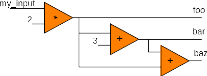
The circuit calculates outputs from input values and intermediate results. Assignments are blocking, so intermediate results are available when they are needed.
Non-blocking assignments
Non-blocking assignments are used to express concurrency in hardware. A non-blocking assignment in Verilog / SystemVerilog is expressed by the <= operator. With non-blocking assignments, the execution of the code continues before the assignment happens. The following statements still use old values of variables in the right-hand side (RHS) expression.
always @(posedge clock)
begin
  foo <= my_input * 2;
  bar <= foo + 3;
  baz <= foo + bar;
end
The body of the clocked process expresses which registers are updated with which values. With non-blocking assignments, all assignments are executed at the same time. The expressions on the right-hand side are evaluated first, and then the calculated values are assigned to the variables on the left-hand side. For the calculation of bar and baz in the above example, the old values of foo and bar, which were calculated in the previous clock cycle, are used. Note that the following piece of code would return the exact same result:
always @(posedge clock)
begin
  baz <= foo + bar;
  bar <= foo + 3;
  foo <= my_input * 2;
end
The circuit synthesized from the above code would look like this:
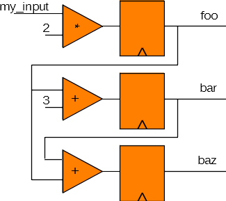
When a clock tick comes in, all registers copy the value from their input to their output, and keep the output value stable until the next clock tick. Then, values ripple through operators, producing new input values for the registers by the time the next clock tick comes. Operators may be simple arithmetic, as in the example, or they may be more complex, involving multiple arithmetic and conditional operations.
To block, or not to block?
As a general rule, combinational logic should use blocking assignments, and synchronous (clocked) logic should use non-blocking assignments. Functions have no notion of time and should always use blocking assignments.
Special cases: blocking assignments in clocked processes
A couple of cases exist in which blocking assignments can or must be used in synchronous logic:
- Loop variables always need blocking assignments, so the loop body executes with the correct value of the loop variable. If a loop variable were to be assigned in a non-blocking way, the loop would execute without an up-to-date loop variable, and the result would be incorrect.
integer i;

always @(posedge clock)
begin
  for (i = 0; i < 10; i = i + 1) begin  // loop variable: blocking assignment
    bar[i] <= foo[i];                   // register: non-blocking assignment
  end
end
- Complex expressions If a design contains complex expressions, intermediate variables are helpful to make the code more readable and easier to understand. In a synchronous process, these intermediate variables must use blocking assignments so their value is assigned immediately.
The following example is based on a simple image processing algorithm. In each clock cycle, we want our circuit to calculate the color gradient in one place, i.e., for one (x, y) pair, and place the result in a register.
// p[x,y] are pixel color values (grayscale)

always @(posedge clock)
begin
  // intermediate variable: blocking
  gradient_X[x,y] = p[x+1,y+1] + 2*p[x+1,y] + p[x+1,y-1] - p[x-1,y+1] - 2*p[x-1,y] - p[x-1,y-1];
  gradient_Y[x,y] = p[x+1,y+1] + 2*p[x,y+1] + p[x-1,y+1] - p[x+1,y-1] - 2*p[x,y-1] - p[x-1,y-1];
  // register assignment: non-blocking
  gradient[x,y] <= gradient_X[x,y] + gradient_Y[x,y];
end
With intermediate variables, the code is easier to read than in the example below:
// Bad example!
always @(posedge clock)
begin
  gradient[x,y] <= p[x+1,y+1] + 2*p[x+1,y] + p[x+1,y-1] - p[x-1,y+1] - 2*p[x-1,y] - p[x-1,y-1] + p[x+1,y+1] + 2*p[x+1,y] + p[x+1,y-1] - p[x-1,y+1] - 2*p[x-1,y] - p[x-1,y-1];
end
Verilog / SystemVerilog assignments in Sigasi Visual HDL
Ensuring these conditions are met is not straightforward. On top of this, they can make the design harder to understand.
Sigasi solves this as Visual HDL instantly analyzes your code as you type, providing immediate feedback based on an extensive set of code linting rules to validate your HDL design. This feedback helps you write correct code right away, which saves you time and your company money as it avoids debugging later on, or taping out a flawed chip.
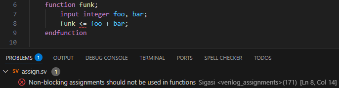
Sigasi Visual HDL flags an error on-the-fly if a non-blocking assignment is used in a Verilog function (linting rule 41: Non-blocking assignments are not allowed in functions) , and can flag a problem for the same issue in SystemVerilog functions (linting rule 171: Non-blocking assignments in functions).
As Sigasi’s code linting rules checks for non-blocking assignments in functions, you don’t have to worry about them anymore. In the example below, Visual HDL flags an error for a non-blocking assignment in a function.
What about VHDL?
In VHDL, we observe a similar distinction between variables and signals. Variable assignments (in processes!) are immediate, so they behave like blocking assignments. Signal assignments happen at the end of the time step, and behave like non-blocking assignments. VHDL also has two distinct assignment operators: := for variables (blocking) and <= for signals (non-blocking).
Also in VHDL, Sigasi Visual HDL catches the incorrect use of assignment operators and other problems to assure a first-time-right design.
Conclusion
In this article, we have discussed blocking and non-blocking assignments in Verilog and SystemVerilog. Generally, non-blocking assignments are for clocked logic, and blocking assignments should be used everywhere else.
Free webinar
In Sigasi Visual HDL, these rules can be disabled for your project, or their severity and parameters can be modified in the project linting settings. Learn more about Linting with Sigasi Visual HDL in our free webinar.
See also
- ANSI and Non-ANSI Port Declarations in Verilog (blog post)
- Sigasi's Software Development Kit Part 2 (legacy)
- Sigasi's Software Development Kit Part 1 (legacy)
- Choose your Verilog formatter (screencast)
- Case statements in VHDL and (System)Verilog (blog post)